Continue to Site

Eng-Tips is the largest engineering community on the Internet

Intelligent Work Forums for Engineering Professionals

  • Congratulations KootK on being selected by the Eng-Tips community for having the most helpful posts in the forums last week. Way to Go!

Column-Isolated Footing joint 1

Status
Not open for further replies.

abdallah hamdan

Structural
Oct 13, 2021
32
If I consider that the Column-Isolated Footing joint is pinned
what are the requirements or details needed to correctly represent the pinned joint in the structure?
 
Replies continue below

Recommended for you

If the column base plate has tightly spaced anchor bolts clustered near the geometric center of the base plate the loads applied to the top of the pier might be a pinned connection to the isolated foundation. i.e. most PEMB columns. But if the anchor bolts are spread out and located near the ends of the base plate and if the design engineer supplies moment reactions at the top of the piers the connection at the top of the isolated column foundation probably needs to be designed as a fixed base column connection. i.e. bracing wind posts and stepped or separate crane columns.


hope the answer is clearer than mud.


Jim


jimstructures, I think OP is asking regarding the connection detail between the concrete pedestal/column and footing joint if connection is assumed pinned.
 
thanks, Jim and MSUK90, MSUK90 is right I need the detail between "the concrete pedestal/column and footing joint if the connection is assumed pinned."
 
MSUH90,

I always design my foundation piers to pad connection with the moment added by the horizontal load/reaction applied at the top of the pier, i.e. xx" above pier to pad connection so there is always a moment connection at the pier to pad location. With the pier/column vertical rebar bent at 90 degrees at the bottom of the column/pier and tied to the matt of rebar.

The frame analysis software does not know how the foundation is designed or detailed. The software model I use is not sophisticated enough to design the foundation at the same time.


Jim

I hope this clarifies my thinking.


Jim
 
Do you need the connection to take moment? If not, the assumption of a pinned connection is likely conservative. True pinned connections in concrete structures are rare and almost always unnecessary.
 

ABdallah hamdan,

You may post more info . regarding the reason for the pinned connected foundation .. If the ground conditions are poor and difficult to provide fixity , pinned connection to the ftg may be preferred..
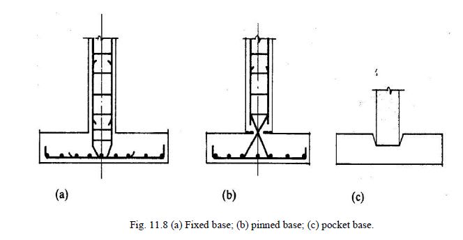
I looked to some books for old but not GOLD details;
One of them ,
( ref. Reinforced Concrete Design to Eurocodes by BHATT,Thomas J. MacGinley )

fixed_pinned_pocket_oder_socket_base_v3xbsm.jpg


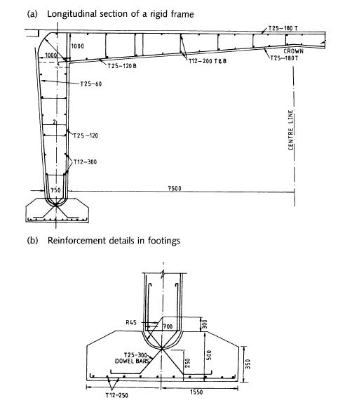
Another example, the bridge pier pinned conn. for rigid frame bridge )
( ref . Structural detailing in concrete by M. Y. H. Bangash )

rigid_frame_bridge_pier_pinned_base_obvj8o.jpg


If the reason for pinned connected ftg is poor soil conditions, still you can provide rigid connections with grid foundation..The grid beams would be designed for the frame moments while the spread ftgs at nodes for vertical loading..
 
c) is bad... don't consider using it. An idealised pinned joint is silly and almost never happens... equally silly is casting the column on 2" of foam and have a single #11 bar in the middle...

Rather than think climate change and the corona virus as science, think of it as the wrath of God. Feel any better?

-Dik
 

True and a BPS for your respond..
But still you may see pin connected piers at existing some old bridges in Europe .
So, i said OLD BUT NOT GOLD detail and did not suggest ..
 
I have seen typical details as shown in figures (a) and (b) shared by HTURKAK.
And I also have seen many engineers say that a footing can not be considered fixed if the soil condition is poor. However, I believe that if we check a footing(soil) for all serviceability checks, then there is no wrong in assuming a base as fixed.
Can you people give your views on my understanding HTURKAK, dik, hokie66?
 

ENG. MSUK,

There are other options .. You are not required to transfer the fixed moment to the ftg.. Pls look to the following doc. ( 5.5 BASE FIXITY ) for partial fixity..( copy and paste from my previous post )

Other option, you can use grid foundation and provide full fixity for weak soils ..


I remember HENRY FORD's quote ; “A customer can have a car painted any color he wants as long as it’s black''

But still you have options ..some of them ; brown black, blue black, very very black, shiny black, dark black....
 
HTURKAK, Thanks for the response. The link you have shared isn't showing any data in my browser.
 
HTURKAK, Thanks for sharing the document.
I have read the section 5.5.
I still have concern why a base SHOULDN'T be assumed fixed if every service and ultimate limit state is satisfied(even if the soil is weak)?
Secondly, lets say a steel column is resting on a pedestal which is supported by an isolated footing. Even if the connection between steel column and pedestal is assumed pinned, the connection between the joint of pedestal and footing(and footing and soil) can't be assumed pinned in my view as the horizontal force will try to rotate the footing.
Am I deflecting somewhere else?
Sorry if the question seems illogical.
 

I do not look to web frequently..just see your post ..
Short answer to your questions;

- You can assume fixed base when you provide reasonable fixity for connection to pedestal and for the footing.. Compare the angular stiffness of joint and the foundation .. ( in most cases it is difficult and more costly to provide fixed conn. and rigid ftg. when weak soil ..........)
- You can assume pinned conn. and provide tension element or SOG could be designed to resist horizontal forces for the steel portal frames

Long answer,

- pls look to the following attached doc.
- Look to the ( Structural Steel Semirigid Connections: Theory, Design, and Software (By Faella, C., Piluso, V., Rizzano)
- You may try to post your specific question within new thread to get better responds...
 
 https://files.engineering.com/getfile.aspx?folder=91a38b59-4bee-44f4-b699-747a90c8a236&file=CONN._Structural_Modelling_(xxx).pdf
Status
Not open for further replies.

Part and Inventory Search

Sponsor