Eng-Tips is the largest engineering community on the Internet

Intelligent Work Forums for Engineering Professionals

  • Congratulations waross on being selected by the Eng-Tips community for having the most helpful posts in the forums last week. Way to Go!

Column steps down in size at the baseplate level 4

Status
Not open for further replies.

Amar Yarli

Structural
Jun 12, 2017
8
GB
Hi,
I am checking a baseplate drawing where the column is stepped down in size at the baseplate connection (image attached) to avoid the requirement for a large moment connection and many bolts.
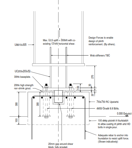
Column_at_base_kbv8fl.png

I have not received calculations yet. The steel structure is subjected to seismic and wind loading along with dead and live loads.
Please let me know if this any recommended practice for a simpler baseplate connection design.

Regards,
Amar
 
Replies continue below

Recommended for you

What is your position in the project, and why are you performing this check?

A degree of thought has gone into this base detail. It is not just about the baseplate and bolt design, but also about limiting the moment on the footing. That being said, I think there are some problems with the detail, but would like to know who I am talking to, responsibility wise, before making suggestions.
 
Hi,

Thanks for your response. I am a Structural engineer and working for a material handling company. We have given this design (Silo Structure) to an external structural consultancy and I required to review and give my comments on the design. As I said, we havent received any calculations yet but the designer claims that the column steps down in size at the baseplate connection to avoid the requirement for a large moment connection and many bolts. This seems bit unusual and hence want to know if anyone came across such designs.
 
Odd. It "could" work, because the column-baseplate connection "begins" acting like a 3-way pinned connection (it permits rotation in all three axis).

But.

They MUST restrain all other moments at ALL of the remaining connections to the foundation somehow with other bracing or thicker walls or some combination of the two.

Also: There is a "reason" for the very large 610x305 vertical. How is that load coming down the large 610x305 being handled by the much smaller "baseplate" column, then through the baseplate to the concrete below? You've got very high loads in a very small space, adding to the twisting loads of the "psuedo-pinned connection" .
 
Hi,

The designer is justifing this as an engineering solution to a practical problem and if we connect this 610 UB directly to the foundation with a full baseplate, it will attract a bending moment, and we will need to design the connection and the foundation to resist the full design bending moment, or risk bolt failure. This would be in the region of 385kNm. Across a 600mm lever arm this generates a pull out force of 641kN.
Please let me know if anyone came across such baseplate connection detailing ?
This is just a 5mX5mX12m(ht) steel structure to support a Silo with four columns with Seismic, wind, content, live and dead loads.
 
Why not just tighten the bolt spacing up significantly, i.e. put them inside the flanges, then you essentially have a pinned connection. This seems kind of unstable.
 
"This is just a 5mX5mX12m(ht) steel structure to support a Silo with four columns with Seismic, wind, content, live and dead loads."

In stead of a portal frame, a braced frame for this structure seems more reasonable, UC section for column is a suggestion.
 
Hi Istructeuk,

Since, truck access is required, we can only brace two oppposite sides of the frame and other two sides are portal frames.
 
Amar,

How high is the truck? The structure can be divided into 2 levels, bottom level with beam and haunch connections.
 
This is quite possibly the oddest column-baseplate detail I have ever seen. It seems like the column would fit on the concrete, so it does not look like there are any geometry related issues. I don't see how reducing the column section eliminates a moment connection. You can design it as a pinned or fixed connection using the larger column section and locate the anchor rods accordingly.
 
One thing that runs through my mind when I look at this is: it's performance during a seismic event. (I.e. will it hinge at this location when/if it's not suppose to?) If I were you (if a high Response Modification Factor is used in the design).....I would consider over-designing this by quite a bit. .....and also what this will mean for the rest of the Lateral Force Resisting System.

 
OP said:
the designer claims that the column steps down in size at the baseplate connection to avoid the requirement for a large moment connection and many bolts. This seems bit unusual and hence want to know if anyone came across such designs.

Baring some extenuating circumstances that I may not be privy to, I think that your concern is justified. The detail is expensive, unconventional, and likely will not achieve the desired intent in my opinion.

This is probably a version of a common mistake that designers make: assuming that reducing the lever arm on your connection tension and compression forces somehow creates a pin. It doesn't. Rather, it often makes things worse by simply creating a moment connection even less capable of resisting moment than what you might have had to begin with.

An exception is where some element of the reduced connection is designed to fail in ductile manner well before the other, brittle failure modes. That's possible here but, based on the proportions, I doubt it. I'd want the stub at least 400 long were I to intend a hinge to form within it. And the anchor bolts don't look to be embedded too deeply given how stocky that shear block looks. And then, what's your uplift capacity on the connection once you've yielded the base in flexure?

I'd be reaching for a better explanation or my red pen. Well, red Bluebeam mouse point thing.

I like to debate structural engineering theory -- a lot. If I challenge you on something, know that I'm doing so because I respect your opinion enough to either change it or adopt it.
 
That's one bizarre detail.

Similar to what jayrod typed, why not use four anchor rods as closely spaced as practical and select the plate thickness for axial load only? The resulting base plate will be thin, so the base plate won't behave like a moment connection. This is done all the time on regular gravity-column designs.
 
I think the detail has merit. I would consider that an effective pin to prevent excessive bending on the plinth and footing.

My main reservations about the detail are not about the structural steel part, but what comes below. It looks like that is being left to somebody else. I would want those bolts to go down a lot further to take an uplift of 300 kN, so they would need to be placed with the footing, whatever that is. 300 kN is about 13 m^3 of concrete, if dead load is what resists the uplift.

I can't see a size for the shear block, or any welds shown. Maybe those are specified elsewhere.

20 mm is not wide enough for grouting the base plate as well as the shear key.
 
one has to go to great effort and detail to attempt a full mom conn or pinned conn @ the base pl...that being said, there is probably no such condition as fully fixed or pinned only a design that approaches either one based on the details...
I have also never seen a detail similar to the one the OP presented, although interesting, I would be wary of using it for the following reasons...
I do not know how it would affect the stability/capacity of the main col...
I would prefer any yielding that may occur to be confined to the base pl/fdn...
Jayrod's suggestion of placing the AB's inside the col fla's would work for me if one is concerned about any significant mom being present...

 
The gravity load at the base of the column is not shown on the detail. How much bearing area do you need on the concrete? One way might be to size the shear block large enough for the concrete to resist the gravity load as well, and just leave out the grout between the pedestal and base plate. That way, you can omit the extra fabrication involving the 200UC which you and others find too complicated.
 
@kootk,

even if the bolts are outside column flange, shouldn't it still be considered "pinned" as long as the structure is laterally stable?
since engineer wants a pinned base plate then structure is stable and regardless if bolts are outside or inside column flange, it should be assumed pinned in the analysis.
 
@delagina:

It may be appropriate to consider the base pinned in the analysis for drift and beam column design. I don't feel that it's appropriate to consider the base pinned for the design of the base itself however. A conventionally detailed base plate is fixed... until it's not. And if the anchor bolts tear out of the concrete in the process of the connection becoming "unfixed", then uplift capacity is over and done.

I see these base connections as rotational springs. If the lever arm on the bolts is reduced by half, then the spring stiffness is reduced by something on the order of half. But the joint doesn't just magically turn into a pin. Half of an objectionable, monstrous moment is what after all? It's a half-objectionable, half-monstrous moment (borrowing form the distributive law of algebra here). Any anchor bolts present -- and now working with half their original lever arm -- need to be designed for the half-monstrous flexural tension that results.

I like to debate structural engineering theory -- a lot. If I challenge you on something, know that I'm doing so because I respect your opinion enough to either change it or adopt it.
 
@kook,

For a simple steel structure with anchor bolts outside column flange, it's assumed pinned for the structure design and do a 2nd analysis where support is assumed fixed for base plate, anchor bolt and foundation design? I don't usually do a 2nd analysis, I assume pin or fix and design "eveything" based on that assumption.

Sorry for hijacking this thread. This will be my last question related to OP.
 
I've been employing one of two strategies for moment frames:

1) run the 2nd analysis and design for 50% of that base moment.

2) design in a ductile failure hierarchy. Steel failure before concrete.

Lots of folks do it your way. Most I reckon. You'll get no judgment from me.


I like to debate structural engineering theory -- a lot. If I challenge you on something, know that I'm doing so because I respect your opinion enough to either change it or adopt it.
 
Status
Not open for further replies.

Part and Inventory Search

Sponsor

Back
Top