Continue to Site

Eng-Tips is the largest engineering community on the Internet

Intelligent Work Forums for Engineering Professionals

  • Congratulations SSS148 on being selected by the Eng-Tips community for having the most helpful posts in the forums last week. Way to Go!

Columns of SMRF supported by beams in one orthogonal direction only 5

Status
Not open for further replies.

Ratsvein

Structural
Mar 3, 2019
10
Hi, I am designing a three story building. with the ground floor as a parking area, second floor as an office, and third floor as a gymnasium/court. The building will be designed as a Special moment concrete frame. The columns up to the third floor frame will have beams in both orthogonal direction, however since the gymnasium/court needs to have an open space, all interior columns is discontinued at the third floor framing and only the exterior columns will continue to support the steel trusses of the roof. The said exterior columns are then connected to beams in one orthogonal direction only. My question is do I have to design the top columns as a cantilevered columns (R = 2.2) and the lower floors as SMRF (R=8.0) when using ELF method or just design the entire structure with R = 8.0? Thanks!
 
Replies continue below

Recommended for you

The roof columns will have different R values for twp different orthogonal directions . R=2.2 for cantilever direction and R =8.0 for the frame direction (connected with periphery beams).

IMO, the roof truss to column connection should be more concern rather than R values.If you release the conn. detail, you may get better opnions.
 
What is your lateral force resisting system above the gym level?
 
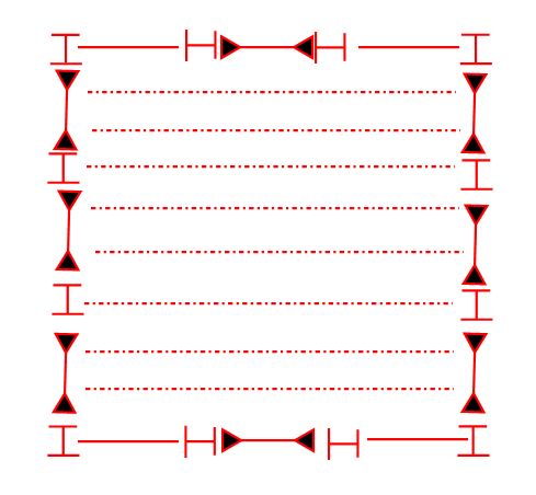
I think that we need more detail on your upper floor level in order to make a robust call on this. Were it something like I've shown below, I'd call that R=8 for the entire structure.

c01_bav4gh.jpg
 
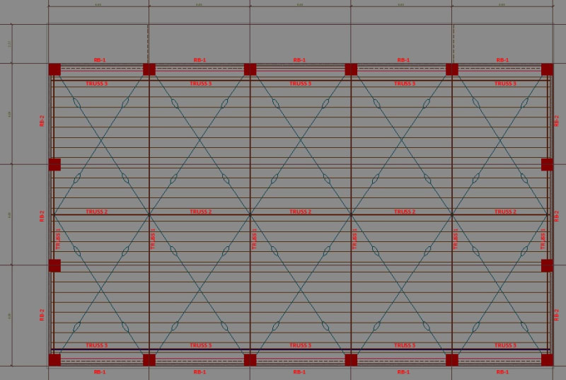
Thanks for your inputs. The said roof framing is shown below.

rooflevel_okjbko.jpg
 
So you've got perimeter beams all around then, right? Are they steel or concrete?
 
columns and beams are concrete while all trusses are steel members
 
Just want to add this to the discussion as a word of precaution. Ignore it, if you’re already aware of the added implication of the R factors.

R factor is used to reduce the earthquake elastic design force by taking the advantage of
1. Energy dissipation capacity of joints and,
2. Redundancy of the framing system.

The basic concept of R factor is that, if say R=8 is used to design the SMRF, then the frames can take only 1/8th of the actual seismic forces within the linear elastic stage. The remaining part is taken care by considering the ductile inelastic displacement/capacity of joints or frames. Frames are not specifically designed for this required quantity of ductility; rather we designed our structures by following the code specified detailing guidelines to achieve the required ductility.

Thus, it is important to identify those joints/frames, which play key role in dissipating this energy, and then make sure it has the ductile capacity to perform as assumed in the analysis and design.
 
This case is an example to say, devil is in the details. The bldg has three storeys ,and the top storey is gymnasium. The clear storey ht should be in the range of 8.0 m for gymnasium floor while in the range of 3.0 for parking and office floors.

The structure will be designed as SMRF implies , the bldg is at high seismic zone. The roof columns connected with spandrel beams all around , that is the intermediate roof columns at facade (except corner columns) will have beam conn. only at one direction.

Another issue, due to storey ht, it is hard to provide strong column-weak beam concept.

IMO, if the structure is SMRF , ductile detailing will govern rather force is divided to 8.0 or 2.2 since the seismic wt of roof is too low.

My country is at high seismic zone and in past, i designed similar strucures.

My suggestions will be;
i = Determine the size of periphery columns at gymnasium level and do not reduce the sizes for the 1st and 2nd storey
ii = Extent the column ht to support the roof trusses from the top chord level so you can delete TRUSS 3's, TRUSS 1's at gable walls.( you can use gable beams instead of trusses)
iii = Provide bracing at top chord level only at one bay.
iv = Provide perimeter tie beam at intermediate level.
v = The truss base plate - column conn. should be pin conn. provide slotted holes at one side.

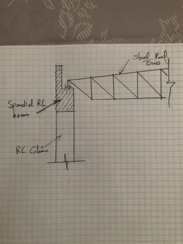
I attached a sketch which i used in past.


roof_trs_cnnIMG_1352_tevh4q.jpg
 
@HTURKAK: Excellent contribution on this. As I'm prone to doing, however, I'm going to question some things.

HTURKAK said:
The roof columns connected with spandrel beams all around , that is the intermediate roof columns at facade (except corner columns) will have beam conn. only at one direction.

1) I suspect that this was the source of OP's original discomfort but, frankly, I don't see it as an insurmountable issue. In the global sense, the frame will require lateral stability at the roof level. That's okay though as there should be a competent, and apparently discretely braced, diaphragm at the roof level for this function. For the local / torsional stability of the roof beams, it would obviously feel better to have those tied into a concrete roof slab. This is, of course, non-mandatory with the right beam proportions however. I'd expect a capable designer to do exactly as you've done in your latest sketch: make the beams stocky to preclude torsional buckling issues. Most codes will also have some minimum requirements for beam stockiness when plastic hinging is anticipated.

HTURKAK said:
Another issue, due to storey ht, it is hard to provide strong column-weak beam concept.

2) One thing that will help to mitigate this is that is generally not necessary to enforce strong column / weak beam behavior at roof levels.

HTURKAK said:
iii = Provide bracing at top chord level only at one bay.

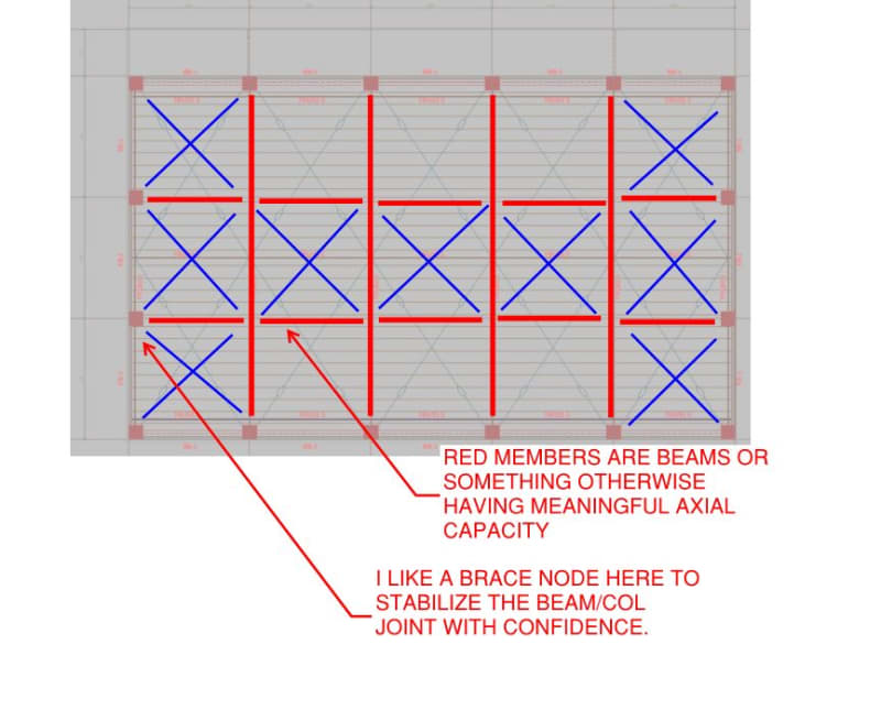
3) While I agree that some optimization may well be possible, I think that a stiff and capable diaphragm is critical here so I'd not be scrapping too much of it. In fact, as shown below, I feel that some additional node points on the left and right may be in order.

4) HTURKAK said:
v = The truss base plate - column conn. should be pin conn. provide slotted holes at one side.

4) What is the basis for your recommendation. Per [1], I feel that it is important that the roof trusses laterally brace the tops of the columns. They can't perform that function with slotted holes at the connection.

HTURKAK said:
iv = Provide perimeter tie beam at intermediate level.

5) I had the same thought, initially, but am conflicted having thought about it in greater detail:

a) It feels good to have some extra joints in the upper story to yield and dissipate more energy.

b) It feels good to reduce the slenderness of the tall, upper story columns. That only helps in one direction of course.

c) While it feels good to create sort of a faux uniformity of story height in this way, it must be remembered that it is really the interplay of story mass and story stiffness that we're trying to manage rather than one variable or the other in isolation. To this end, having a light story (steel roof) combined with a flexible story (tall columns) might actually be beneficial for creating a uniform shear building response up the height of the structure. Admittedly, this is something that is difficult to "tune" reliabley.

d) At the end of the day, I suspect that OP is stuck with some kind of vertical irregularity with or without the intermediate framing level.

c01_kjpqy1.jpg
 
Dear KootK (Structural)

I will try to reply your questionings to my best knowledge;

KootK (Structural) said:
....the frame will require lateral stability at the roof level. That's okay though as there should be a competent, and apparently discretely braced, diaphragm at the roof level for this function.

Providing diaphragm at the roof level with horizontal bracing of steel roof trusses is an option but i will prefer this alternative , for the frames with steel columns. In this case,with RC columns this option will not be cost effective.
KootK (Structural) said:
2) One thing that will help to mitigate this is that is generally not necessary to enforce strong column / weak beam behavior at roof levels.
This is true ...it is hard to satisfy strong column /weak beam concept for the top storey of multistorey bldgs and signle storey buildings . However, in this case, the expected location of the plastic hinge is at the top of the column rather than at the bottom.
KootK (Structural) said:
3) While I agree that some optimization may well be possible, I think that a stiff and capable diaphragm is critical here so I'd not be scrapping too much of it. In fact, as shown below, I feel that some additional node points on the left and right may be in order.
I proposed bracing of one bay , IMO, in this case, steel roof with RC columns bracing is necessary for the stability of roof elements rather than providing horizontal support to RC columns .

KootK (Structural) said:
4) What is the basis for your recommendation. Per [1], I feel that it is important that the roof trusses laterally brace the tops of the columns. They can't perform that function with slotted holes at the connection.
I recommended slotted pin conn. in order to reduce the temp. effects and axial force demand at seismic loading.

KootK (Structural) said:
iv = Provide perimeter tie beam at intermediate level.

5) I had the same thought, initially, but am conflicted having thought about it in greater detail:

Although it is not defined, i think the exterior walls are. Providing tie beam at intermediate level is essential for confining the masonry walls during seismic loading and will reduce the slenderness in one direction, so one can use rectangular column rather square.
The original thread was for the R value. The use of higher R value will not provide exemption for drift requirements. I am retired engineer. My suggestions based on real experience and observation of bldgs aftermath of heavy earthquakes rather than the codes which are changing at every 4-5 years.

I think we are too differnt time zones and cost of steel and concrete.


I call it a zero sum game.

Ever since the code created the "seismic response factor", engineers have falsefully trying to find justifications that allow the select of a higher R value, thus lower the initial seismic load. The falseness is realized until the end of the game, that is, for a certain framing system, the ductility/serviceability control the effort of the design.

I am not an expert on seismic considerations, please correct me if my comment is erroneous.
 
Status
Not open for further replies.

Part and Inventory Search

Sponsor