Eng-Tips is the largest engineering community on the Internet

Intelligent Work Forums for Engineering Professionals

  • Congratulations waross on being selected by the Eng-Tips community for having the most helpful posts in the forums last week. Way to Go!

Combination Retaining Wall and Foundation Wall 2

Status
Not open for further replies.

CSFlanagan

Structural
Mar 17, 2006
23
US
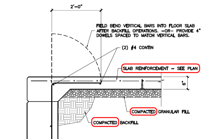
I'me designing a foundation for a pre-engineered metal building warehouse addition. Because of the existing site topography, the building will sit on reinforced concrete walls that range from 4' to 12' tall. I've designed the walls as cantilvered retaining walls, because after the walls are constructed, the INTERIOR will be filled with #57 stone and a concrete floor slab will be poured. (This is fairly typical of a dock wall for trucks, but these walls are typically only 5 feet tall.)
So the wall starts out as a cantilevered retaining wall, and ends up as a propped basement wall supported at the top of the wall by the floor slab, which is tied into the wall at the top with rebar. The faces of the wall will have stress reversal, meaning the inside of the wall will start in tension as the back-fill stone is filled, then then the exterior face will be in tension once the floor slab (and floor loads) are applied. It's the reverse of your typical basement condition
One thought is that the the wall essentially becomes pre-stressed during the back-filling, and the load reversal is insufficient to overcome these initial stresses.
I've looked through my resources and cannot find a similar example to definitively illustrate how to design for this situation. I was hoping someone ha encountered this situation and can help?
 
 http://files.engineering.com/getfile.aspx?folder=b13f7b65-120c-4668-8d46-bc7a2cdf0d0d&file=Wall_Section.pdf
Replies continue below

Recommended for you

I'm interested to hear input on this too.

A related question I have is your development length for the vertical #7 bars. Even with the hook into the footing, I don't think they are fully developed.

The max moment occurs at the construction joint, so I believe you will need 19" (fc'=3000) to develop the #7. That translates into a 22" thick footing.
 
Some questions:

...then the exterior face will be in tension once the floor slab (and floor loads) are applied.

How will the floor slab and floor loads on either "compacted backfill" (called for on the drawing) or #57 stone (mentioned in the thread) put the exterior face in tension?

What is the "slab reinforcement", welded wire fabric? If so, WWF in not reinforcement, with significant ability to resist tension, just crack control... at best.

Beam_Deflection_-_2_Loads-1_pvame6.png


[idea]
[r2d2]
 
More questions:

How long do you think it will be between wall/slab pours? If it's not long maybe they keep their forms/braces for the wall in place until the slab is poured and cured, I'm not aware of any ill effects of leaving forms on too long but its possible there might be.

Will there be any kind of heavy machinery on the pad to spread the gravel or for whatever reason after the wall is poured? It's unlikely that the compacted backfill itself will apply any significant pressure on the wall in the short time between wall/slap pours, thats kind of already the case as theres not any horizontal restraint provided while cutting and forming the wall but surcharge load from heavy machinery could be a problem.

That being said I think a 15" wall calls for a double mat regardless. And a small reinforcement area will probably cover for your potential tension load on the exterior face.

@SlideRuleEra, Do you think WWF is really insufficient for resisting a uniform tensile load even if you supply enough steel area and strength? I don't have a definitive answer for that, I rarely spec it but I'm curious to hear your thoughts. Either way if the metal buliding has heigh push out loads at the base, I would try to use the slab to resist that by putting hairpins around the anchors and having rebar tension ties running between columns.


JoelTXCive: I am using the "standard" design from the CRSI Design Guide (2014 Edition). My old 1984 CRSI book has similar dimensions. Running this through RISA Foundation typically produces slightly different results, but I have not done that as of yet. Your point about development is well taken, but a closer look at CRSI standard tables makes all of the retaining walls suspect.
 
SlideRuleEra: Very good questions and points.
The application of the floor load (say 250 psf) will exert downward pressure on the soil/stone fill, thereby creating some outward pressure on the wall. With the wall stem now pinned top and bottom by the slab and footing, the wall becomes a simply supported vertical beam instead of a cantilever as it was originally constructed and loaded. As I said, this reversal may not be enough to overcome the initial stresses from the backfill operation, but the loads are definitely there.
It doesn't show in this sketch, but we typically extend the rebar further into the slab. The 6x6-W2.9xW2.9 wire mesh does contribute some tensile capacity to the slab. The metal building columns have hairpins at the column base to return the outward column reactions to the slab. The slab acts as a horizontal beam. In addition, we design the column as a 2' taller wall (following the AASHTO recommendation for highway surcharge listed in the CRSI tables), so the retaining wall would be capable of supporting the loads without pinning the top... in theory. But since we have to pin it anyway, I'm just trying to determine the effect on the wall with the load reversal.
Thanks for the reply!
 
dnlv:
The wall will be constructed using SYmons forms, with forms on both sides, and snap ties through the wall to connect the forms. There is minimal bracing to hold the wall vertical and true. The inner ply will be removed before backfilling, so the outer ply will provide little bracing.

We are planning to use #57 stone for fill, and a "rock slinger" conveyor to place it. We typically use a walk behind vibratory compactor to ensure there are no voids, but the clean stone is pretty much "self consolidating" as it is placed. So there are not any large lateral loads on the wall during the backfill operation using clean stone. However, we have a good supply of engineered fill close by, so there "might" be a chance to use compacted soil material. Or the next project may require engineered fill. (We just did a smaller foundation with the walls only 5 feet tall, so the loads were minimal and I was not as concerned as on this one.)

I'm thinking a 15" wall will require some temperature steel at leas on the outer face, but the CRSI tables don't call for it. I am looking into it further. Maybe using the temperature steel on the outer face can allow me to analyze it as a double reinforced member, and reduce some of the bar sizes on the inner face. I will also run RISA Foundation to see what that comes up with.

Thanks for the input!
 
ACI 318-14 Section 11.7.2.3 says that all walls greater than 10in need two layers of steel EXCEPT basement and retaining walls.

With that being said, we usually have temperature and shrinkage steel on the front of our walls. We usually do a grid of #4's or #5's at 12".

We always compare our final retaining wall designs to publicly available plans that TxDOT has available (I think CalTrans and Florida DOT have posted plans too):

ftp://ftp.dot.state.tx.us/pub/txdot-info/cmd/cserve/standard/bridge/rwstde05.pdf

We compare dimensions and reinforcement to the highway standards. With the exception of development lengths, the TxDot plans are pretty conservative designs.
 
CSFlanagan - I like your 15" thick wall; don't think it will need any "help" from the slab. In fact, capping and tying to wall to the slab may create other "problems"... will get back to that in a minute. Do a agree with dniv and JoelTXCive that a second rebar mat in the wall is a good idea. So much for my opinions, here are my numbers:

#57 Granite @ 103 lb/ft[sup]3[/sup]. Since it will be "consolidated" with a small vibratory compactor, used 115 lb/ft[sup]3[/sup].
#57 Granite, Angle or Repose: Have seen values from 35[sup]o[/sup] to 45[sup]o[/sup]. Used 40[sup]o[/sup].
Horizontal Equivalent Liquid (EL) Pressure = 25 lb/ft[sup]2[/sup]

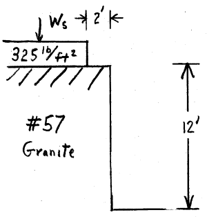
The 6" slab (75 lb/ft[sup]2[/sup]) plus the 250 lb/ft[sup]2[/sup] Live Load create a 325 lb/ft[sup]2[/sup] surcharge on the #57 Granite backfill.
Surcharge Load (lateral pressure on the wall) = 71 lb/ft[sup]2[/sup]. Actually, this load is probably even a little lower... will get back to that, too.

Below is all of this graphically, more or less drawn to scale. The surcharge load is less than 25% Edit: 50% of backfill load. Yes, it's resultant force is a little higher (6' above the bottom for the surcharge compared to 4' for the backfill), but not much.

Surcharge-3_dveyeu.png


Now, for why I believe the surcharge lateral pressure is < 71 lb/ft[sup]2[/sup]. The 6" slab is heavily reinforced (#7 @ 9" oc.) for almost 2'. This "somewhat" cantilevered slab will pickup much of the 325 lf/ft[sup]2[/sup] surcharge load. Have not done these calcs, but a more accurate loading diagram may be something like this (Note: I know this is over simplified, but retaining wall calcs have so many variables that the whole process is an approximation)
Surcharge_Setback-1_aqtnh6.png


Now back to the 6" slab with 6x6-W2.9xW2.9. That size mesh has 2 each, 0.192" diameter wires per ft. of width (0.058 in[sup]2[/sup]/ft of width).
Consider a #3 rebar (0.375" diameter, 0.11 in2 crossection). The rebar equivalent to the WWF is #3 @ 22" oc. (0.060 in[sup]2[/sup] / ft of width).
#3 @ 22" oc. (or the specified WWF) won't do much.

IMHO, if the wall tries to move because of the surcharge load, the slab will crack (and move) where it has only the WWF.

Finally, the backfill is good quality and well consolidated, but it varies in thickness (4' to 12'). I would be more concerned with (very slight) differential settlement cracking the slab. Also, 6" thick seems "thin" for an heavily loaded (250 lb/ft[sup]2[/sup]) floor on backfill. I would be more comfortable with, say 8" thick, with a significant rebar mat, and the slab is "floating" (i.e. not attached) inside the walls. Let the 15" thick walls, with 2 rebar mats, deal with the horizontal forces... no help from the slab needed.

Edit: I see now my calcs deviate from your drawing somewhat. For example, wall height is 11' (not 12') above average grade. Also the 6" slab (75 lb/ft[sup]2[/sup]) is part of the (11') backfill, not the surcharge; therefore p[sub]s[/sub] = 54 lb/ft[sup]2[/sup] (not 71 lb/ft[sup]2[/sup]). Net result: The surcharge is less of a "problem" than I calculated... but will leave the post unchanged, concepts is still the same. If you wonder where I "dredged up" some of this info, let me know.

dniv - Will make a follow up post on your question.

[idea]
[r2d2]
 
dniv said:
Do you think WWF is really insufficient for resisting a uniform tensile load even if you supply enough steel area and strength?

That is a well-worded question. Start with the terminology. Today, Welded Wire Fabric (WWF) can be very different from Welded Wire Reinforcement (WWR).
Part of the problem with WWF is it's flexibility - very hard to get (and keep) it in the correct position in a relatively thin (say 6") slab. During concrete placement, typically the WWF is stepped on, or "mashed" into the subbase at numerous places. Of course it is worthless at the very bottom of the slab. Per your question, if there is enough steel and it is positioned in the right place... yes it will work as intended. With WWF it is hard to get "enough steel" and to have assurance it is positioned correctly. Also, with WWF need to place joints using exactly the same logic needed for plain (unreinforced) concrete.

WWR can be essentially a manufactured mat that should perform equivalent to field-tied rebar of comparable size.

A good resource on both products is the Wire Reinforcement Institute.

For what it's worth, I quit using WWF in the mid-1980's and went with either fibers, rebar, or just an extra 1", or so, of plain concrete - depending on the application. This was for industrial projects where lowest first-cost was not top priority.


[idea]
[r2d2]
 
SlideRuleEra, thanks for the explanation, makes perfect sense to me. What exactly is the difference though, between WWF and WWR? It seems like the terms are commonly used interchangeably. .
 
dniv - That is the type info the Wire Reinforcement Institute provides (link given above). In a "nutshell", WWF is flexible wire welded together, WWR is rigid steel rods welded together (but not without the deformations characteristic to rebar).

See High Strength Welded Wire Reinforcement Compared with Rebar... and

Provisions in ACI 318 for Structural Welded Wire Reinforcement ... and

Manual of Standard Practice--Structural Welded Wire Reinforcement

In general, industry "associations", "institutes", "organizations", etc. are a great source of information (much of it both technical and free). When working with unfamiliar products or materials always search for the appropriate "trade group".

[idea]
[r2d2]
 
SlideRuleEra, I'm familiar with the product and I've read plenty of WRI's literature, but I'm missing where they differentiate between WWR and WWF, and appear to use the term reinforcement and fabric interchangeablely. If your saying the difference is whether it is a small enough gauge that it can be coiled I get it, but the only explanation I've seen is in the Manual of Standard Practice and it says "Welded wire, sometimes called fabric or mesh is what we refer to today as “STRUCTURAL WELDED WIRE REINFORCEMENT (WWR)” for concrete construction." If Im just being dumb and missing it I apologize, it seems we're really just talking semantics anyway.
 
dnlv - You are not being dumb... I am underestimating your experience and apologize.

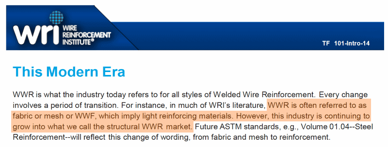
Your mention of wire being small enough to be coiled is a good working definition of WWF - even if it is purchased in flat sheets (easily damaged during concrete placement). I believe confusion comes from the product's history and industry changes over time. The Institute's history publication even hints at that (see the image below).

My subjective interpretation of the term WWF is the problem small gauge products. WWR includes both WWF and the larger rod products which are reasonable substitutes for rebar. Therefore, an Engineer has to proceed carefully - use precise, accurate technical terminology to ensure the correct product will be incorporated into the work.

WWR-History-1_dx8cer.png


[idea]
[r2d2]
 
Status
Not open for further replies.

Part and Inventory Search

Sponsor

Back
Top