Eng-Tips is the largest engineering community on the Internet

Intelligent Work Forums for Engineering Professionals

Combined Controls Extension 4

Status
Not open for further replies.

axym

Industrial
Apr 28, 2003
1,043
0
0
CA
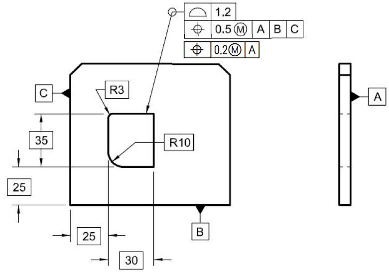
Here is Figure 8-24 from Y14.5-2009, with an additional position tolerance added:

Fig_8-24_with_Boundary_Orientation_e9erl2.png


The additional callout refines the relationship of the feature to Datum A.

Is this a valid application? ;^)

Evan Janeshewski

Axymetrix Quality Engineering Inc.
 
Replies continue below

Recommended for you

pmarc,
You are right, I didn't take into account the profile tolerance zone is not constrained in orientation. Thank you for pointing that out.
So eventually there is a refinement of 0.2 to orientation, resulting from the specified value of 1.
I don't like the indirectness of it.
I guess that's why I brought up "each line element" - more straightforward = less trouble in practice and more useful. Much like in the case of composite profile vs. profile + position boundary dilemma.
 
pmarc,
Regarding your answer to chez311 - we've seen that the composite profile tolerance, in terms of tolerance zones, provided the same flexibility for production as the profile+ MMC position with it's bonus. That is with the additional advantage of design intent clarity and less "unexpected" scenarios.
 
semiond,

It is your right to like or dislike whatever you want - just like I have a right not to like position wrt A applied to a single feature of size that is nominally perpendicular to datum A. My opinion is that as long as a geometric control or a combination of geometric controls does not clearly violate any rule from the standard, it is at least worth considering.

Another thing is that geometric tolerancing is not only to define the end product in full and unambiguous manner. It is also to provide as much tolerance as possible within "boundaries" determined by functional reuquirements. So if using more generous tolerancing scheme (position + profile combo vs. composite profile OR perpendicularity @MMC vs. each line element perpendicularity) does not interfere with the design intent, I do not think the scheme should be replaced by something else just because this something else is more straightforward.
 
pmarc, I agree with almost everything said, And by the way, I too don't like "position wrt A applied to a single feature of size that is nominally perpendicular to datum A." Why not use perpendicularity?

However you mentioned that MMC position + profile combo vs. composite profile that we discussed earlier, is a comparison by which MMC position + profile comes out as the more generous tolerancing scheme. I'm not sure why you still stick to this viewpoint, after we've seen with the help of your excellent diagrams that the tolerance zones in these 2 cases are equally generous and behave almost the same, with the exception of the unwanted behaviour of the profile + MMC position that widens the RC boundary just a little bit (In my opinion, such "generousity" won't do any good).

I agree that all legal tolerancing schemes are legitimate and should be available to choose from, but sometimes there is a clear advantage to one over the other, that should be pointed out.
 
semiond,
The point of my excellent diagrams, as you called them, was exactly to show that the 2 cases are not equally generous. If they were, we would not be able say that certain condition of the as-produced feature meets one scheme and does not meet the other.
 
pmarc,
I looked at your diagrams once again.
We calculated the same MMB (VC) and LMB (RC) boundaries that appear to be equivalent for both controls. Yes, I know the rotation phenomenon for the profile+position combo makes a difference and widens the LMB boundary in a peculiar way, but it didn't even make you update calculated 10.1 LMB width/height to a larger value, and for a good reason.

The 2 schemes not equally generous?
If you choose to call the phenomenon that caused the feature pass one control and be rejected by the other generous, so be it. In this particular case - I'd rather call it dangerous :)
 
semiond,

It is the second time in last few weeks when I have a feeling that no matter what I will say I will not convince you. So with almost no hope of success I will leave you with following example:

In Y14.5 world, if a cylinder of nominal diameter 10 is controlled with tolerance +/-0.1, this requires that the cylinder must be produced within 9.9-10.1 size limits and must have perfect form when produced at MMC.
If the same cylinder is controlled with basic size 10 and profile tolerance of 0.1, this also requires that the cylinder must be produced within 9.9-10.1 size limits and must have perfect form when produced at MMC, but in addition it also means that the cylinder must have perfect form when produced and LMC.

Rethorical question #1: Are you able to say which of the two schemes is more generous?

Rethorical question #2: If from functional point of view it does not really matter if the cylinder, when produced at LMC, has perfect form or not, does the first scheme deserve to be called dangerous? Or should we rather say that the second scheme is too restrictive?
 
pmarc,
I do understand the point that you convey with the rethorical questions.
But please notice that I emphasized the words "in this particular case" in my last post.
I learned to never make generalizations, unless those generalizations are narrow enough to describe a very unique type of cases. A pin produced in a way that it meets local size limits in every cross section but somewhere it violates the perfect form boundary at LMC is not necessarily a bad product, in many cases it's good enough for it's function.
That leads to absolutely no conclusions about a feature that is toleranced in way that, in your own words:"may lead to some unexpected and undesired consequences."

Edited for typo correction.
 
pmarc,

I think your last post summed it up nicely, I see the point you are trying to make and can appreciate it. Whereas the second scheme may be more restrictive/conservative in most cases this is not necessarily desired, especially if its not required for the function of the part - just as we wouldn't apply the most restrictive tolerances to a part unless required. Of course this means that in every case, especially with more generous tolerances or shapes with larger radii/circular sections, we must analyze whether the chosen scheme might result in unwanted behavior, but that goes without saying.
 
chez311,
You summed up nicely what I tried to sum up ;-)

I read somewhere some time ago that applying a GD&T to fully and unambigously define product is like being at Level 1 of the game. As long as an individual or organization does not apply the GD&T (so that as much tolerance as possible from functional point of view is available), Level 2 will remain unreachable.
 
I just want to add to pmarc's last remark my observation, that Level 2 is only available to "design players" working in organizations where the people "playing" at the production floor have enough spare time at their work day to interpret sophisticated feature control frames using colourful tolerance zone diagrams and making fun calculations, in order to get just a little bit of extra tolerance "bonus" that they are probably not going to utilize anyway.
That is instead of the boring practice of just reading the limits directly from a simple and unambiguous specification, which finds a way to both make sure part functionality AND enough flexibility for the technologist to conduct an efficient and manufacturable process.

If you work in the kind of organization I described, adopt Level 2 strategy and have fun. If the latter boring option is more suitable to your situation, you better stay at level 1. :)
 
semiond said:
.....working in organizations where the people "playing" at the production floor have enough spare time at their work day to interpret sophisticated feature control frames using colourful tolerance zone diagrams and making fun calculations, in order to get just a little bit of extra tolerance "bonus" that they are probably not going to utilize anyway.

That is instead of the boring practice of just reading the limits directly from a simple and unambiguous specification

Someone, on this forum, said:

..... But that is the price of simplicity - the requirements become tighter. With GD&T there is usually a trade-off between tolerance and complexity - to allow more tolerance, the specification (or inspection method) must be more complex.

 
semiond,
In order to get at level 2 organizations do not have to use what you called "sophisticated feature control frames". In many cases proper, that is functional, datum feature selection is well enough to be able to open up tolerances to a point where everyone benefits by that. This is just one example and there is much more that can be done without even stepping into the unsafe/uncertain teritory of extensions of principles or sophisticated callouts.

Side question: Could you please stop making allusions to my "colourful graphics full of fun calculations" if you do not understand what they are for here? Over and out.
 
And one more for the other side of the argumnet argument:
“The law of diminishing returns means that even the most beneficial principle will become harmful if carried far enough.”
 
greenimi,
I appreciate your second quote very much - that was said much better than I could ever say to express my message.

But please allow me to use your first quote with a little modification - I will replace just one word by a one that is closely related to it and more relevant to this discussion and it's specific context, and let's see what comes out. This is also for the benefit of others that may have misunderstood me:

"..... But that is the price of simplicity directness - the requirements become tighter. With GD&T there is usually a trade-off between tolerance and complexity - to allow more tolerance, the specification (or inspection method) must be more complex."

Does that statement still make sense? No? I don't think so too.
Well, by simplicity I did mean clarity, and directness. Sometimes you can have more direct specifications than others, that supply the same useful flexibility for production, and an advantage of better product definition, even if they don't include the M in a circle symbol or require calculations to determine the total size of the usable tolerance zones.
I'm not against MMC position in general. It is often very useful, direct, efficient and unambiguous - particulary with the axis interpretation. But here we saw a specific example where it may be less preferable.

I have no clue why pointing it out causes such a fierce resistance.
 
pmarc,
Regarding the level 1/2:
I can justify aspiration to get to level 2, as long as what it takes to be at level 2 doesn't come in expense of the main goals of the strategy of level 1 which you described: "fully and unambigously define product".
With modern production equipment, many manufacturers do not get to the extreme boundaries of the allowed tolerance zones, and certainly don't utilize the whole range. If giving the that little extra tolerance comes at the expense of clarity of design intent, and with the price of allowing "unexpected" things like we've seen - which means more ambiguous product definition, this may lead to damaging consequences.

All I'm saying is - there are 2 different aspects that should be considered. There is no reason to emphasize one and present it as a more advanced level, and underestimate the other. Each one should make his choice, but bear in mind the two sides of the coin.

Edit: By the way, I'm sorry if I made it look like I was sarcastic towards the effort you've done with the figures. I appreciate them, they were useful for me and contributed a lot to this discussion. I just wanted to convey the point that manufacturers don't always have the luxury to make the best value out of such specifications through tolerance analyzis. And often a more straightforward approach is more appreciated. I'm sorry again if you found the way it was conveyed offending.
 
Status
Not open for further replies.
Back
Top