Continue to Site

Eng-Tips is the largest engineering community on the Internet

Intelligent Work Forums for Engineering Professionals

  • Congratulations SSS148 on being selected by the Eng-Tips community for having the most helpful posts in the forums last week. Way to Go!

Combined footing outside of middle third 7

Status
Not open for further replies.

Jamie112

Industrial
Nov 29, 2020
8
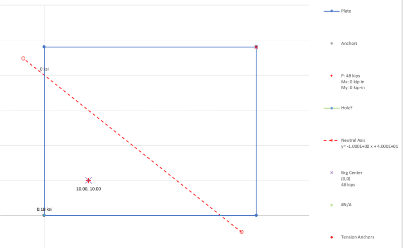
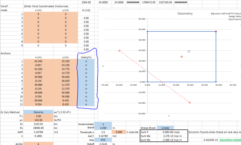
I know how to analyze when resultant force is outside of middle third in one direction. But how do you analysis when the load is eccentric in both direction and at least one of them is outside of middle third? I tried to use software called TEDDS and it says it fails once it is eccentric in both direction and one of them is outside of middle third but then I tried other software it doesn’t report failure but cuz there is no detailed computation I cant verify how they comp it.
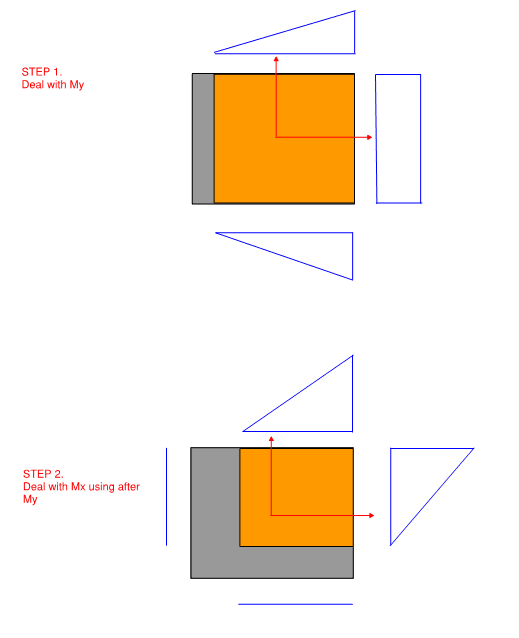
My understanding is do one direction first and take the length of non-zero reaction zone as the width when calculating the other direction. Is this correct?
I guess eccentric footing in both direction is quite common for say raft supporting core walls?
 
Replies continue below

Recommended for you

I'm not aware of any closed form solutions for biaxial eccentricity for foundations, however a possible solution method would be adapting the rigid plate analysis from here: Link

You have the three static equations of equilibrium:
sum P = 0
sum Mx = 0
sum My = 0

and three unknowns
Bearing Depth, Y
Neutral Axis Rotation, alpha
Peak Bearing Stress, sigma

For the process described in the linked file an Ok start point for the three unknowns is:
Look at the footing as a normal elastic cross-section
Sigma = max compression from P/A +- Mx/Sx +- My/Sy
alpha = Elastic Neutral Axis Angle (90 degrees + Elastic Axis = line between point of max compression and tension)
Y = Depth to Elastic Neutral Axis (distance from max compression to point of 0 stress on the Elastic Axis)

Example:
4 ft x 4 ft foundation (0,0) = bottom left corner
P = 48 kips applied at (10,10) or ex=-14 in, ey=-14 in
Using a sign convention of -Mx = Compression on +y and -My = Compression on -x
P*ex = -56 kip-ft
P*ey = 56 kip-ft

Initial guesses:
Sigma = 0.09375 ksi (13.5 ksf)
alpha = 2.3562 rad
Y = 43.639 in

A solution with Tolerance below 1E-13 kip-in for the moments is found in 5 iterations:
Sigma = 0.18 ksi (25.92 ksf)
alpha = 2.3562 rad
Y = 28.2843 in

Capture_jgpwn9.png


Spreadsheet: Link
Derivation of P, Mx, My from the perimeter lines using a linear stress model:
piecewise_linear_derivation_1_hukdlf.jpg

piecewise_linear_derivation_2_dyzyhj.jpg


My Personal Open Source Structural Applications:

Open Source Structural GitHub Group:
 
Thank you Celt. I will have a look on the link and the spreadsheet before I comment further.
Just a quick one. How do you analyze raft supporting core walls, which is quite common to be bi-eccentric loaded then?
 
Usually like to keep within the kern zone for things like elevator/stair cores. Can Serve as a quick secondary check on overturning stability.
Once inside the kern can use any of the various design software or hand calcs.

If space constraints are forcing you into a condition where the footing can’t be made large enough to get in the kern. Then I’ll check overturning stability a couple of ways by hand and use a more advanced software package to model a plate on springs to do the bearing checks, software options are RAM Concept, RISA-Foundation, Sp-Mats

My Personal Open Source Structural Applications:

Open Source Structural GitHub Group:
 
Thank you.
So I had a look on the link and the spreadsheet you provided. However, the pad here has no rods to hold the tension so I believe it is a different scenario.
My thought is shown as below. Is this a correct approach or am I missing anything? I know the stress at the corner will be quite a lot but if it is still within ultimate bearing capacity, can I say it is ok?
bi-ecc_gadnau.png
 
Do you remember how to find the minimum/maximum stress for doubly symmetric beam with skew loads? You shall add the term P/A in from of the bending stress terms. If a portion of the footing is inactivated by tension, you need to find the neutral axis, and iterate the calculation until the entire base is in compression. It is a long and difficult procedure, I would avoid it if possible.

Suggest to do a quick check om δz = P/A ± Mx/Sx ± My/Sy. If δz is greater than/equal to zero, you are good to go. If it is less than zero, increase the base dimension to reduce the influence of the moment in that direction.

 
Jamie112 said:
..the pad here has no rods to hold the tension..
Right still a similar process just leaving off the Tension components from the anchors, in the spreadsheet I linked to set all of the Use toggles for the anchors to "n". edit: Clicking the Attempt General Solution Button it will pop up a couple dialog windows because the first solver it tries to use depends on the anchors being there but the second solver which it will initiate after the first one fails will find a solution for the no anchor case.
Capture_vkkuy1.png


Jamie112 said:
..can I say it is ok?
The bearing may be ok but you'll still need to check global overturning.

My Personal Open Source Structural Applications:

Open Source Structural GitHub Group:
 
-Retrograde
Thank you for the textbook.

-r13
Yeah. P was not in that pic I uploaded just for clarity.

-Celt83
I will double check on the spreadsheet and see how it goes and will be back if I have problems. Overturning will be checked. I was concerned because like I said, some software simply says it fails once resultant force falls outside the kern area for a bi-eccentric footing before checking the overturning. So (I understand it is not preferred but) can I say as long as the overturning and pressure are okay, it should be allowed to have bi-eccentric footing even if it is not in kern?

 
Celt83:
I am just going through your spreadsheet; what is the purpose of the sheets: User_Inputs and Shapes? I've never tried to draw either input or output data; is there a good tutorial for this... or, I can search the web.

Rather than think climate change and the corona virus as science, think of it as the wrath of God. Feel any better?

-Dik
 
dik:
The sheet is a bit of a work in progress. Eventually those tabs will have much simpler inputs for the geometry and I plan to do some templated shapes and the output tab will be formatted for letter size printing and only include the relevant result data.

Right now the sheet can be a bit intimidating to use so I'm trying to make it more user friendly.

Jamie112:
...it should be allowed to have bi-eccentric footing even if it is not in kern?
this becomes a condition where you need to consult with your projects Geotechnical Engineer as once you get a highly concentrated corner a lot of the assumptions for the allowable bearing value they provided become invalid.

My Personal Open Source Structural Applications:

Open Source Structural GitHub Group:
 

Thanks... looks great and am trying to follow it through. I've not graphed data before and it looks a little imposing... but, will work it out. Again thanks... it's a wonderful work in progress, and much appreciated.

Rather than think climate change and the corona virus as science, think of it as the wrath of God. Feel any better?

-Dik
 
Will do... and, again thanks.

Rather than think climate change and the corona virus as science, think of it as the wrath of God. Feel any better?

-Dik
 
Nice job Celt! I loved seeing the simplicity of your solution. A solution based on simple statics. Then use the computer for trial and error rather than trying to come up with a complex exact formula. Very elegant.
 
Thank you JoshPlumSE!

I do have to admit it took the better part of almost two years to relearn the calculus to do that line integral stuff to be able to work out P and M’s from the stressed area.

My Personal Open Source Structural Applications:

Open Source Structural GitHub Group:
 
Status
Not open for further replies.

Part and Inventory Search

Sponsor