Continue to Site

Eng-Tips is the largest engineering community on the Internet

Intelligent Work Forums for Engineering Professionals

  • Congratulations KootK on being selected by the Eng-Tips community for having the most helpful posts in the forums last week. Way to Go!

Combined footing problem

Status
Not open for further replies.

LoadSlayer

Structural
Jan 28, 2024
9
Hi,

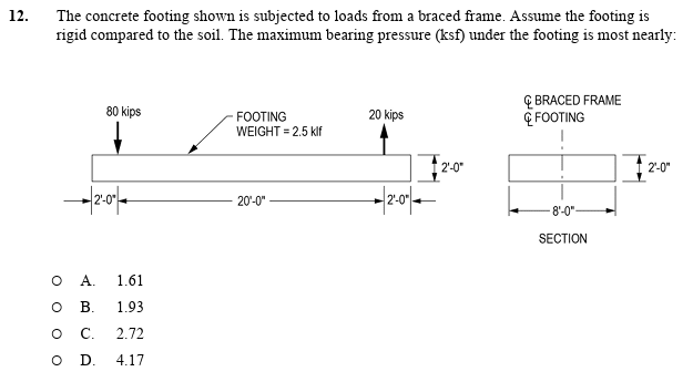
could anybody help me solve this problem? I tried to solve it and I got the answer B. But the solution key shows C.
Please see the picture below:
Capture_a1dkoq.png
 
Replies continue below

Recommended for you

You'll need to determine the location of your resultant load on the footing.
The magnitude of force at this location is equal to: 80k + 2.5klf x 24ft - 20k = 120k

From the left edge of the footing
•Find the sum of moments (stabilizing & destabilizing) acting on the footing:
(-80k x 2ft) - 1/2(2.5klf)(24ft)² + (20k x 22ft) = -440k-ft

•Determine the location of the resultant load from the left edge:
-440k-ft + 120k(X) = 0
Solve for X, X=3.66ft

•Determine the eccentricity from the centerline of footing:
e = L/2 - x = 12ft - 3.66ft = 8.34ft (left of centerline)

Since e > L/6, that is... when eccentricity is greater than the kern:
qmax = (2P) / [3B (L/2-e)]
qmax = (2 x 120k) / [3 x 8ft (12ft - 8.34ft)] = 2.73ksf
 
Thanks @StrEng007 for your response !

Could you please let me know what is wrong with this solution?
qmax= (60/24*8)+ (100*10*12*12)/(8*24^3)+ 2.5/8 = 1.93 ksf
 
As StrEng007 has demonstrated, we need to check the location of the force resultant against the footing's kern.
Your solution incorrectly assumes there is no uplift on this footing.

The P/A + M/S approach can only work when the entire surface of the footing is in contact with the soil.
 
Got you!
So within L/6 from the center line both ways where we can guarantee that the whole footing will be under compression?
But why L/6? and why qmax = (2P) / [3B (L/2-e)?

Thanks for your patience.

 
See this thread: Link

As to why L/6 this is the kern, think of the footing as if it were just any other beam section loaded with P and M. Assuming all the normal beam stuff the top and bottom stress would follow P/A +/- M/S.

S = bL^2/6
M = P*e

So the second term becomes:
P*e*6 / b*L^2

If e = L/6 then it becomes
P/b*L or P/A

So the case where e=L/6 is the point where the stress becomes 0.

Beyond that eccentricity the formula is no longer valid because there can be no tension component from the soil, see the linked thread for the development of the formula for this case.
 
Aha. Now it make more sense.

I read the part of the thread for deriving qmax. It was helpful.

Thanks Celt83.
 
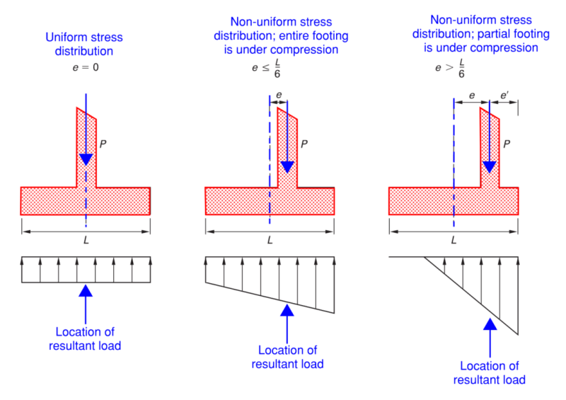
Here is a graphical explanation of what Celt83 was referring to.

Notice in this example, the moment is generated from a single applied point load with a given eccentricity. The combination of that axial load (P) and the eccentricity (e) creates the overturning moment.
This OT moment can be determined for an arrangement of multiple loads as illustrated in my first post where I consider the stabilizing and destabilizing moments.

Screenshot_2024-03-02_094301_uuouxs.png
 
Status
Not open for further replies.

Part and Inventory Search

Sponsor