Eng-Tips is the largest engineering community on the Internet

Intelligent Work Forums for Engineering Professionals

Combined Instrument Transformer Failure on 1 Phase

Status
Not open for further replies.

NAZ55

Electrical
Oct 24, 2007
211
0
0
US
Hello All, One of our high voltage combined instrument transformers has failed and has to be replaced. I am trying to figure out a way where the secondaries of the remaining two CIT's could be used to create voltage and current for the missing unit for a balanced 3 phase power system.

Will greatly appreciate the help on this matter.
 
Replies continue below

Recommended for you

Also, just to clarify by combined unit, I mean it's the instrument transformer where both the CT and PT are combined in one housing.
 
If you use secondaries of other 2 phases for the other phase, then your metering as well as protection will malfunction. Recommended to replace the fault unit as soon as possible

Thanks,
Vijay
 
It depends on what the CT and VT secondaries are connected to. It may be possible to jury-rig something on a temporary basis, but may be impossible if you rely on phasor summation for ground fault detection.

The unit needs to be replaced. There is no other real solution.
 
If it feeds only metering, you may be able to get by multiplying the readings by 3/2.
ConEd did that when a plant under construction had the same problem. Load was balanced and light ( < 10% of CT) so the error wasn't large. Both parties agreed to the temporary fix for a couple months.

Some protective relaying won't work without the third phase. You can approximate the missing current by Ia + Ib = -Ic for a balanced load, but as mentioned above, no ground fault protection.
 
I agree with rcwilson with the disclaimer that I would have to see an actual connection diagram to be sure.
I used metering on one line to neutral as a check on a three phase metering scheme that I was using for the first time and was unsure of. There was a close enough correlation between the single phase metering x 3 and the three phase metering to reassure me that the three phase metering was correct.

Bill
--------------------
"Why not the best?"
Jimmy Carter
 
This is a metering Unit. No relay protection is intended. Any modifications would be a temporary fix until the unit is repaired.
 
If loads are balanced, you can convert to 2 element metering. But if this is revenue metering, better discuss with all parties.
 
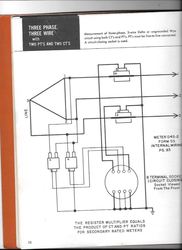
Here is a connection diagram for two element metering.
Voltage is measured across L1-L2 and L2-L3. The scheme meters on the assumption that the voltage is equal on all three phases.
metering_mkyzog.jpg

The accuracy is as good as the voltage balance. If the voltages are balanced, the metering accuracy of unbalanced current is good.
The A phase CT sees the A phase component of C phase and meters the C phase component assuming that the C phase voltage is equal to A Phase voltage.
Likewise B phase CT sees the C phase component of C phase and meters the C phase component assuming that the C phase voltage is equal to B Phase voltage.
We used two element metering for years until we lost one phase of a three conductor submarine cable. A single conductor was laid parallel to the three conductor cable to replace the bad phase. It was about three feet away. This caused a reactive voltage drop on one phase. The unbalance was enough that we could no longer meter accurately with two element meters. We switched our three phase metering to three element meters.
Your question is:
"What is the percentage voltage unbalance and can you accept a similar percentage metering error?"
Bill
--------------------
"Why not the best?"
Jimmy Carter
 
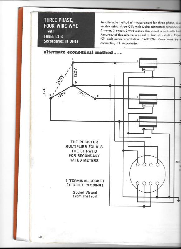
If you are stuck with line to neutral PTs there is another scheme that uses two elements but three CTs.
You may be able to drop a bushing CT over a transformer bushing to meter the third phase current.
I can post the connection diagram if you need it. (The first time that I used this connection was the time that I used the single phase check meter.)

Bill
--------------------
"Why not the best?"
Jimmy Carter
 
That may be resolved by reversing the connections to the third meter element, but the bigger problem is that there will be no voltage for the potential coil associated with the third current element.
I the CT part of the metering transformer is still functional, or if you can get a large enough window transformer to drop over a bushing here is a circuit that will work.
metering01_pnsi5b.jpg

I have used this connection a number of times.
The accuracy is as good as the voltage balance.
If the PTs are connected to A phase and C phase, then the B phase CT forces the current through both A phase and C phase current elements.
The A phase element meters the A phase component of B phase and the C phase element meters the C phase component of B phase.
This will meter unbalanced currents to the accuracy of the voltage balance.

Bill
--------------------
"Why not the best?"
Jimmy Carter
 
Bill,
We don't have spare CT available, nor do we plan on changing any phase to ground connections to phase to phase. Do you know why I am getting A and B phases to be 180 out?
 
I am working with a tiny switchboard, 50kW. It uses two CT's to provide amperage measurement on three phases. I haven't had a chance to dig in to how it works yet.
DSC_2433_dmb8ue.jpg
 
The current is in the reverse direction going through the third current element.
The lack of a voltage for the third element is a problem.
You are familiar with the open delta connection to derive a third phase from two phases and a neutral.
There is a connection called a Winnipeg connection that will develop a third phase for a wye system.
The Winnipeg connection was used for distribution systems.
For metering you could use two small lighting transformers.

I would use 240:480/120:240 volt transformers wired for 240 Primary and 240 volt secondaries.
You will be applying 120 Volts to the 240 Volt windings.
Connect one transformer in parallel with the secondary of each PT.
Connect the secondaries in open delta. The voltage developed across the open delta will be the correct angle to replace the missing phase.
I suggest checking the primary and secondary voltages with a good meter to determine if there is a turns ratio error.
What type of loads do you have?
For most plants that I have seen, the phase current balance is good enough to use a 3/2 ratio.
If you have a lot of single phase loads that tend to be unbalanced, this may be better than nothing.

Bill
--------------------
"Why not the best?"
Jimmy Carter
 
TugboatEng said:
I am working with a tiny switchboard, 50kW. It uses two CT's to provide amperage measurement on three phases. I haven't had a chance to dig in to how it works yet.

If it's a three wire system, all you need is two. The un-metered phase amperage will be the phasor sum of the two metered phases.
 
If your original metering is a 3-element (3-phase, 4-wire wye) configuration and your load is fairly balanced, your meter would register approximately 2/3 of the correct figure. As a temporary fix, you need to multiply by 3/2 (as mentioned by rcwilson) the meter registration to arrive at the approximate correct figure.

Regards.
 
With regards to your temporary CT connections, I think the meter will see symmetrical current phasors (120 degrees apart) because of the way the CT secondaries are connected to the meter.

Since the sum two currents (Ia + Ib) is equal to -Ic and -Ic enters the phase C current coil in the opposite direction, the meter will see an Ic current at the correct phasor position.

If your meter has the capability to display the current phasors, it would probably be showing the correct current phasor sequence.
 
Status
Not open for further replies.
Back
Top