Continue to Site

Eng-Tips is the largest engineering community on the Internet

Intelligent Work Forums for Engineering Professionals

  • Congratulations IDS on being selected by the Eng-Tips community for having the most helpful posts in the forums last week. Way to Go!

Combined pad and strip foundation

SidC95

Civil/Environmental
Dec 24, 2024
1
IMG_20241224_170742.jpg
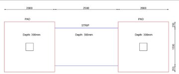
I have to design a series of pad foundations that will be tied together by a strip foundation. Each column will carry about 600 kN. Between the columns there is a masonry wall that will be built from the foundation level to the ground floor level. My main concern is the influence of the strip foundation on the pad foundations. For now I have designed the pad foundations as 2m by 2m pads. Only bottom reinforcement has been used. Is it possible that the strip foundation might increase the internal forces near the supports? The reinforcement in the pad foundation is a lot more than in the strip foundation. Minimal reinforcement was used in the strip. I need some guidance concerning this issue. The plans have already been approved by my superior but I still have my doubts.
 
Replies continue below

Recommended for you

The idea behind adding a strip beam between two footing pads is that, due to the added beam stiffness, you can assume an equal pressure distribution under each pad of
q= (Point Load 1 + Point Load 2 + Self weight all elements) / (A1 + A2) (q=0 under beam).

With the pressure distribution known, you can then draw a FBD, and determine the moments and shear acting on the strap beam.

I agree that the pads should only have bottom reinforcement (i.e. negative bending). The beam will need top and bottom reinforcement verify with the FBD.

I hope this helps.
 
What is the distance from top of footings to ground floor? Does the wall load extend over the square footings? Have you considered omitting the strip footing, increasing each square footing to, say 2.5m square and relying on the masonry wall to act as a beam, or adding a slim grade beam, spanning from column to column?

If the strip footing must act as a strap footing between square footings, then top steel will be needed to resist the calculated moment each end of the strap footing as mentioned by Civil Sigma.

If minimal reinforcement is being contemplated for the strip footing, it seems to me that its bearing pressure must be considerably less than 600/4=150 km/m^2, so why is the strip footing so large (1.5x2.5 m)? Why not equalize soil pressure by reducing the width of the strap footing? If all footings have equal bearing pressure, top steel at square/strip footing intersections would be nominal.
 
Why is the strap so wide? Does the wall load require such a wide footing? If the wall (strap) footing needs to be 1500mm wide then ok, but perhaps you should consider revising the footing shape to a rectangle (easier to excavate and form, simpler reinforcing steel arrangement, and easier to design). Design the footing as a single big rectangular footing with uniform bearing pressure and each way bottom bars, and evenly spaced continuous top bars in the long direction. I am assuming there is no net uplift on the footing and the column loads are about the same. (If this was a much thicker footing, I would probably also add minimum uniformly spaced top temperature bars in the short direction for crack control.)
 
It might help if you told us the line load under the masonry wall.

Assuming a line load of w kN/m, the required width of the strip footing is w/150 in order to equalize the soil pressure on all footings. The strip footing will act more or less like a one way double cantilever, but you might want to add top bars parallel to the wall, each end of the strip footing to resist minor moment fluctuations at the ends of the strip footing.
 
The whole thing is one footing. Design as single rectangular footing, including top and bottom reo as needed, including top reo due to the fact the footing will span between the columns and resist the upward load of the soil
 
Tomfh stated: The whole thing is one footing. Design as single rectangular footing, including top and bottom reo as needed, including top reo due to the fact the footing will span between the columns and resist the upward load of the soil.

That can certainly be done, but I don't believe it is economical.

I am assuming that the vast majority of the load comes from the columns. The wall load is presumed to be light enough for a small strip footing, perhaps 600 wide x 200 deep or thereabouts, but certainly not 1500 x 300.

The most economical way to carry the two 600 kN column loads is to use a square footing centered under each column. The little strip footing will not influence the square footing significantly.

 
Last edited:
Is it possible that the strip foundation might increase the internal forces near the supports?

It is. If the wall were to truly deliver it's load uniformly then you would get hogging moments near the joint between the strip footings and the pad footings.

That said:

1) This is a pretty common situation that seems to cause no real world issues. Maybe the joint cracks on to and life goes on.

2) If your wall extends well over the pad footings, the wall may arch / span over the strip footing in service such that it receives little actual load.

The only thing that strikes me as odd about your design is the relative width of the strip footing relative to the pads. I would expect the width of the strip footing t be in the 16" - 36" range. That said, I don't know your loads or your soils so my intuition could be out to lunch.

The only possible change that I feel your design might merit is to simply:

a) design the pads to resist all of the column loads and;

b) design the strip footing to resist only the wall loads.

That may already be the case.
 

Part and Inventory Search

Sponsor