Continue to Site

Eng-Tips is the largest engineering community on the Internet

Intelligent Work Forums for Engineering Professionals

  • Congratulations SSS148 on being selected by the Eng-Tips community for having the most helpful posts in the forums last week. Way to Go!

Combining manifold equasion 3

Status
Not open for further replies.

Helepolis

Mechanical
Dec 13, 2015
206
Hi all,

A little disclosure before my question, the last time I had anything to do with fluid mechanics was 7 years ago so if my question is somewhat trivial don't be too harsh on me.

Now to my questing:
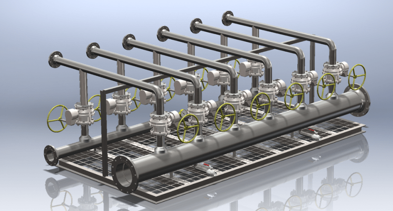
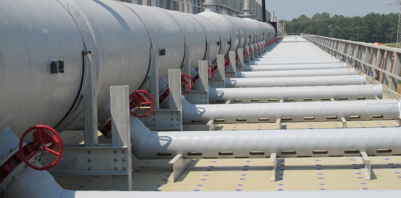
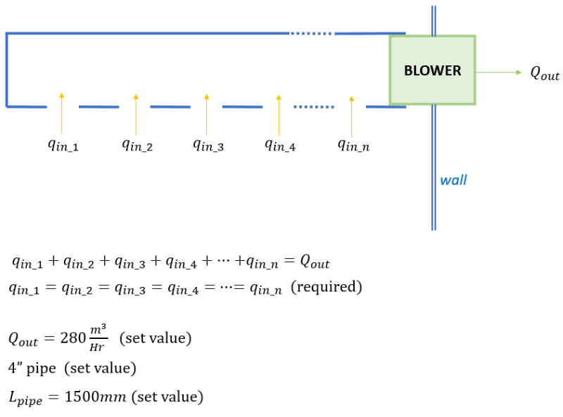
Given that I have (something of) a combining manifold (single outlet and multiple inlets), the structure of the manifold is a straight pipe with a blower at one end (the opposite end is closed) and several inlet openings along the pipe's wall (the inlet holes are on the pipe itself, no extensions).

In case I want equal flow rates from all the inlets, which means that I have to "adjust" the cross section of the inlets (intuitively the closer the inlet to the blower the smaller the opening should be to restrict the flow).
How should I approach this problem, given that the Q_out and pipe dimensions are known.

After searching a bit I found some sources that use the Bernoulli's equation and other sources use the 'generalized macroscopic energy balance', in any case I'm lost.


Thanks,
SD
 
Replies continue below

Recommended for you

There are two ways of doing this.

The easiest is to make the manifold much bigger than the inlets to the extent that any pressure drop along it from first inlet to last inlet is so low as to be able to be ignored. So if you go for double the combined inlet square are you're in a good place.

To be equal flow you then need all the inlets to be fed from the same pressure source and have the same pressure drop for the same flow. DO you? I have no idea as you haven't told me or given me a diagram with data written on it.

Forget Bernoulli for this application.

Or just add a small regualting valve to each inlet and then start with the one nearest the blower and adjust then repeat once you have all the inlets flowing.

Mind as soon as say one inlet then doesn't flow it will alter the balance.

How exact a eqaul flow do you need? 1%, 10%, 25%?

This issue has been discussed many times - try a search for manifolds

Remember - More details = better answers
Also: If you get a response it's polite to respond to it.
 
While there may be some benefit from optimizing the manifold design, in practice, nobody bothers with it. The manifold header is typically the same size as the line pipe.

large_kw2xac.png
 
bimr said:
While there may be some benefit from optimizing the manifold design, in practice, nobody bothers with it. The manifold header is typically the same size as the line pipe.

I disagree. On a well designed manifold, I've never seen the manifold pipe the same size as the individual pipe runs.

CT-FRP-Pipe_nyjfjk.jpg


Use Search, under the thread title between Forums and FAQs, for "maldistribution" and "flow distribution". This has been discussed many times here, and this should hit on the best threads.

Good Luck,
Latexman
 
BIMR - " in practice, nobody bothers with it. "

I tend to agree hence my question about how exact an equal flow does the OP want?

The difference in the sort of header posted by bimr is usually negligible, especially if the inlets are grouped close together and the header size is a decent size. A long header with widely spaced inlets will be a lot different to a short closely spaced one. As usual we don't have a clue at the moment...

Latex mans header is rather extreme and looks like it varies in diameter, but then sometimes I think the process engineers get a bit up themselves....

Remember - More details = better answers
Also: If you get a response it's polite to respond to it.
 
I think "nobody bothers with it" because most don't know how. Realistically, the OP has not supplied enough data to know what their design should look like. That's why I recommended he search the site for the technology so they can figure it out.

Good Luck,
Latexman
 
Thanks all for the replies.
Yeah, I should have attached at least a basic schematic of what I'm talking about.
image_sa6dji.png


In general this is sort of a "though experiment" that got me intrigued enough to dig deeper.
The pressure source is at the outlet and the inlets are just openings in the pipe itself, open to the ambient air of a room.
I really don't need an exact equality between the inlets flow rate, guess a 10-15% deviation will do just fine.
 
Latexman (Chemical) said:
I disagree. On a well designed manifold, I've never seen the manifold pipe the same size as the individual pipe runs.

Latexman, although the entire manifold is not shown in your picture, the particular manifold does not appear to be well designed as it should eventually decrease to the size of one of the laterals. I do agree with you that what you have pictured would require a detailed design.

However, the poster said a "straight pipe with a blower at one end (the opposite end is closed) and several inlet openings along the pipe's wall", not fifty openings. Unless the designer's underwear was a little tight, and he was also having a bad day, nobody would bother with the poster's proposal.

The poster's thought process probably should have considered a more complex example rather than what he initially posted if he was interested in learning about manifold design.

The room duct like the poster has presented would probably be 8-Inch diameter to keep the velocity less than 700 ft/min and using the inlets to control air flow across the room. 8-Inch duct costs $2-3 per foot.

 
As a teenager I helped with many installations for my Dad’s HVAC business. Some were similar to the OP’s thought experiment, just the opposite, positive pressure. The holes in the duct were much smaller than the duct.

Several 8” diameter holes in a 8” diameter duct will have unacceptable maldistribution.

Good Luck,
Latexman
 
That's why the designer would use the same velocity criteria to size the inlets at 4-Inch diameter.
 
In the more common situation where the manifold is on the delivery side of the pump or blower the rule of thumb is to keep the pressure drop along the length of the manifold to less than 10% of the pressure drop through the holes. This should keep the maldistribution to less than 5% with all the holes the same size. I believe this same rule should be applicable to the current example with the manifold on the suction side.

Keeping the pressure drop along the manifold low can be achieved be either oversizing the entire manifold or by stepping it as shown in Latexman's photo. Like everything else in engineering, the decision is guided by economics.

Katmar Software - AioFlo Pipe Hydraulics

"An undefined problem has an infinite number of solutions"
 
katmar, and requirements.

It is a capital mistake to theorise before one has data. Insensibly one begins to twist facts to suit theories, instead of theories to suit facts. (Sherlock Holmes - A Scandal in Bohemia.)
 
Status
Not open for further replies.

Part and Inventory Search

Sponsor