Continue to Site

Eng-Tips is the largest engineering community on the Internet

Intelligent Work Forums for Engineering Professionals

  • Congratulations SE2607 on being selected by the Eng-Tips community for having the most helpful posts in the forums last week. Way to Go!

Combining two streams with different flows and pressure

Status
Not open for further replies.

bmmarti3

Chemical
Aug 14, 2019
6
Pressure_System_viqzn4.jpg


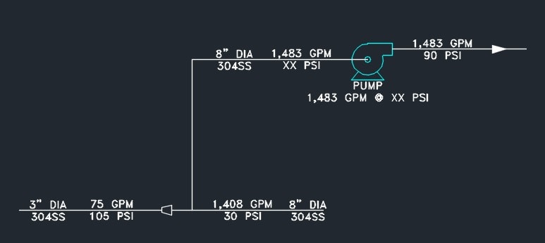
I'm trying to size a pump, but my issue is not being able to determining the feed pressure of said pump. I have a re circulation loop of 1,408 GPM. I am injecting 75 GPM into the loop at a higher pressure than the return loop pressure. Ultimately, the goal is to reduce the boost pressure required on the loop pump since the flow is so large. How much, if any, pressure can I make up with the injection?
 
Replies continue below

Recommended for you

Pressures need to be equal or you will not have flow in the direction you are wanting it to go at the tee. And unless there is a large pressure drop in the suction pipe, you will not have 90 psig on the pump discharge.
 
The pump suction will be the path of least resistance for the injection stream so the flow should go that direction as opposed to back flowing (I think). So, I believe it should work. The pump discharge pressure is the result of the pump. I don't understand your pump discharge comment.
 
We need a diagram of the whole system really.

Is this system a closed re-circulation loop??
If it is the system pressure is irrelevant to the pump differential pressure ( providing the pressure at the highest point is >0 psig)

All you are going to do with the injected fluid is drive the system pressure higher, but this will change the suction and discharge pressure by the same amount, therefore your injection of fluid. Where is this extra fluid (75 gpm) going if this is a re-circulation closed loop?

So this fundamentally does not do what you seem to think it does.

Pressure at the common node point (i.e. the tee) between the 8" pipe and the 3" pipe will be identical. So your diagram is not correct.

To size a re-circulation closed loop pump what you need to know is flow rate of the fluid and the combined fluid friction between the outlet of the pump and the inlet of the pump. According to your diagram this is 60 psi. Adding more fluid makes no difference to this fundamental sizing requirement.

Remember - More details = better answers
Also: If you get a response it's polite to respond to it.
 
Here's an updated full flow drawing

Pressure_System_rev_02_e0fnlt.jpg


I would have assumed X2 to be 30 PSI based on the DP across the membrane filter
 
You need to show all control valves, check valves, and flow elements in order to correctly understand the system. One cannot simply draw assumed flowrates and pressures without supplying control equipment that is used to provde the defined flows. Either the HP pump is a variable speed pump controlliong flow to the downstream recirc system or is a constant speed pump with a outlet discharge control valve and flow element.

"...when logic, and proportion, have fallen, sloppy dead..." Grace Slick
 
The feed pump will operate with a VFD and the re-circulation pump will use a motor starter. The 68 GPM filtrate stream will have a manual throttling valve as well as the 7 GPM concentrate stream. There are no other valves within the loop shown.
 
Well the differential pressure will be 60 psig but the actual pressure at x2 will be quite difficult to maintain as the in flow and outflow will impact on this with no apparent pressurisation tank??

Assuming the pump is close to the filter then a small difference in in flow to out flow will change the actual pressure very quickly.

But the pump differential pressure won't change.

What is this thing?

Remember - More details = better answers
Also: If you get a response it's polite to respond to it.
 
Like stated previously, you need a lot more stuff in your schematic.

How about set your recirc pump at 1408 gpm and TDH to equal 105 psig based on 30 psig (X2). Set your feed pump at 75 gpm and TDH to equal 105 psig, but move the discharge to downstream of the recirc pump with check valves on each to prevent any backflow.

Crude mark up of what I am thinking.
 
 https://files.engineering.com/getfile.aspx?folder=5335d06b-8048-4289-bdc9-fc4ef1e6a9c9&file=Pressure_System_rev_02_e0fnlt.pdf
Ok, I managed to get a little empirical data on the system and I think I resolved my own problem, though not in a satisfying manner. X1, X2, and the pressure out of the feed pump will all be equal. I can use the feed pump to boost that pressure, but it will also boost the back pressure to the membrane filter. I still need the recirc pump to overcome the full membrane filter differential pressure. I was hoping to use the feed pump to boost the loop pressure to reduce the recirc pump size, as a 30 PSI recirc pump is 40 HP vs 75 HP at 60 PSI pump.

As someone asked, this is a ceramic membrane filter for wastewater applications.
 
Looking at it a bit more, I am uncertain about something. There needs to be some type of material/mass balance on the system. All the "filters" I have dealt with have an influent (dirty), a permeate (clean) and a concentrate (dirtier). You are showing the recycle coming off the filter. Where on the "dirty scale" would that be? Is there a possibility of the influent + recycle becoming too concentrated and fouling the membrane?
 
The new feed pump pressure seems about right at 105 psig, since it needs to develop adequate pressure for the case when the membrane filter is clean. Add an FE on this pump discharge to control feed pump speed to get the flow you want, which may not always be 75gpm. Would agree, that when the filter is running dirty/fouled at 60psi dp, suction pressure at x2 would be 30psig.

When the filter is clean and running at low capacity, pressure at x2 will rise and will approach that at min flow operating point for the recirc pump - add a min flow low control loop for the main recirc pump(bypassing the filter)for this case.

Analyse the pressures at these points for both clean and fouled conditions for low throughput/ high throughput subcases to be sure all components can handle these 4 cases.
 
Think you need a control valve on the recirc pump discharge (or VFD) to maintain recirc flow at 1400gpm, else the pump will run out to end of curve when the filter is clean.
 
T'was me I'd put a check valve in the output of the recirc pump feed the make-up in after it and before the filter. The recirc will reduce its power draw by whatever the feed pump provides directly to the filter.

Control the feed pump speed against the pressure at the filter input. As water leaves the system the pressure will drop - made up by the feed pump.

Keith Cress
kcress -
 
Status
Not open for further replies.

Part and Inventory Search

Sponsor