Eng-Tips is the largest engineering community on the Internet

Intelligent Work Forums for Engineering Professionals

  • Congratulations waross on being selected by the Tek-Tips community for having the most helpful posts in the forums last week. Way to Go!

Compatibility of Ansys Structural

Status
Not open for further replies.

somebodyfromworld

Mechanical
Jul 15, 2015
32
0
0
NO
Hi there
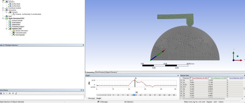
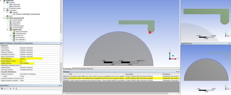
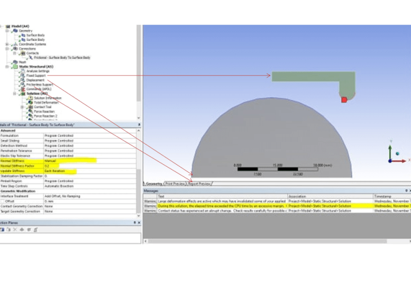
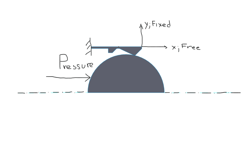
I have a task to check the maximum pressure to push the ball thru. The license I have is only to do a Structural Analysis and not any dynamics. So my question is it possible to push the ball through the apper part using pressure and find out the maximum value for it to pass the restriction. All parts are metal

tempsnip_exdrwb.png
 
Replies continue below

Recommended for you

You can run it static with large deflections on (static, so no dynamics and inertia, which I suppose is fine here), applying an enforced displacement (this can be slowly increased in time) on the side of the ball and pushing it through to the right side.

To get the total load applied, just look on the reaction on the position where the enforced displacement is applied.

 
thanks for reply

For some reason i cannot solve, i haven't tried with displacement yet but using pressure doen't work. Lardge displacement is ON, mesh is very fine (at the contact is 0.05mm) and still get highly distorted elements. Substeps are also very small 10000MAX
 
Unfortunately I cannot open these files.

Below is a small example with the enforced displacement and looking at the reaction there on the sphere (sphere slides on a friction-less support) in order to get the force needed to push through (~22 N). Convergence is definitely much easier if we reduce the contact stiffness to say 0.2 instead of 1 (contact settings, and set normal stiffness to manual with a factor of 0.2). make sure that the contact is not going through though. Also material used is steel for both (2D plane strain).

Hope this helps.

AnsysTest_b6yuh4.jpg
 
Unfortunately I cannot (using an old node limited demo version, not possible to save).

If you have any questions though just let me know.
(Below is an image with the contact settings I described in order to aid convergence, hope it helps)
AnsysTest2_qovnor.jpg
 
the image is very blurry, cant really see any settings. The upper part is fixed to move uppwards, right? Esspecially the right upper corner of it, so it wont lift when the ball is passing thru. I see you include a APDL command there, could you write what is it?
 
The upper part (small beam), is fixed on the left side. The half circular part at the bottom is the one that moves from left to right in the positive x-direction (displacement on bottom left vertex). Finally, the base of the half circular part (bottom edge), has a frictionless support.

Presentation1_ijospr.png

Hope this helps. I am pretty sure you can manage (no time for me to look into this further).
 
Status
Not open for further replies.
Back
Top