Continue to Site

Eng-Tips is the largest engineering community on the Internet

Intelligent Work Forums for Engineering Professionals

  • Congratulations KootK on being selected by the Eng-Tips community for having the most helpful posts in the forums last week. Way to Go!

Complex Hydraulic Synchronising Problem 3

Status
Not open for further replies.

escapizm

Marine/Ocean
May 14, 2013
40
I’m looking for some advice on finalising the hydraulic design on a cable tensioning system.

Four Cylinders are being used to pull a 160 strand cable to 1274t tension over approx. 840mm stroke, the cylinders are 300mm bore x 200mm rod x 700mm stroke. Buckling is ok.

From 0mm to 700mm the load goes to approx. 200te, the next 140mm is stretching the cable and the force rises exponentially to 1274t.

When the cylinder runs out of stroke or the final tension is realised a large jacking nut is threaded down the cable onto a bearing plate, the problem is that in order to install the cable (offshore) the cable is installed with this 840mm slack which as is passed through a U shaped inclined clamp. When the job is done two opposing cable cross in an X shape so the cable end mounting plates are fixed approx. 45 degrees. When we install the slack cable the catenary weight causes the bearing plate to tilt 8 degrees in the mounting plate, analysis has shown a force of 200t is required to rotate the bearing plate.
Link
In order to prevent thread damage it is important to ensure the cylinders all extend in unison, to complicate matters the two cylinders furthest away from the corner of the bearing plate in contact with the clamp are being put under tension “dragging” the rods out of the cylinder (see att. where the hatching indicates high pressure in the cylinder due to the induced load), the two cylinders adjacent to the contact point are being compressed. The hydraulic design must accommodate this up the c.200t load after which the 8 degree gap between the bearing plate and clamp is closed and the force applied by the four cylinders push in the same direction. Various concepts for this control are being considered from individual servo control of each cylinder to the use of an over centre valves with a single directional valve and flow divider, both concepts have yet to be considered fully.

If we pursue a solution with servo or proportional valve controlling each cylinder with each having a feedback loop fed from cylinder mounted distance transducers this could give us a problem. Any error correction in one cylinder will have an effect on the adjacent cylinder as they are all rigidly connected to one another via the jacking plate (cross head), this could give rise to a confused system that may be impossible to operate.

I’m also considering a simplified solution of over centre valves (as shown) in the annulus side of each of the cylinder and piloting open from the full bore, the load induced is approx. 15t equating to 37 bar in the annulus.

I’ve discussed with the leading Servo valve people and they are very nervous of the problem noted above.

Any help would be appreciated.

Regards

escapizm
 
Replies continue below

Recommended for you

If you like PNachtwey's debates, have a read of the "flow makes things go" and the whole pressure is resistance to flow threads on the fluid power forum.

Link

Very entertaining.
 
Folks

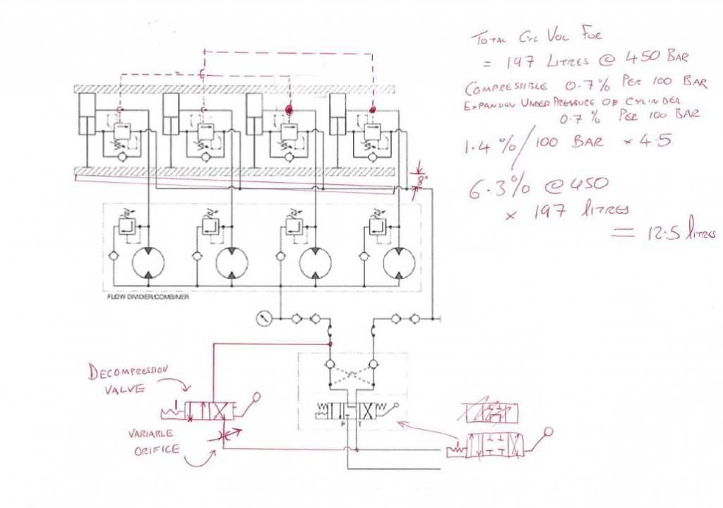
I’ve added a decompression valve (see circuit) in order to avoid and shocks as the assumed 12.5 litres of compressed oil (0.7% per hundred bar for compressibility of the oil and the same 0.7% for the expansion of the cylinder body/pipework = 1.4% / 100 bar = 6.3% @ 450 bar = 12.5 litres)


I am wondering though if I should add some lines to the over centre valve, if you see my original post with the link with the mechanical schematic you will see the full bore of two of the cylinders is always under positive pressure, whils the two furthers away from the contact corner are not.

On that basis will the two closest to the contact point open immediately I permit the oil to flow out of the annulus with a possible delay for pressure build up in the other two before they move? If this was the case I could put a line from each full bore of the cylinders furthers away to each of the over centre valves.

Thoughts?
decomp_zps39fa63c3.jpg
 
I will also remove the PO check as advised, it is not doing anything.
 
Have I read your 1 L/min flow to each cylinder correctly? If so you don’t need 24 servo valves for 4 cylinders.

What is the actual positioning tolerance and expected speed of movement under shock load?

I think a proportional valves with linear feedback will be better than 3% accurate and will provide temperature and viscosity compensation not possible with a gear flow divider. My personal experience with gear flow dividers would make it my last choice for positioning accuracy especially at your working pressure. Gear flow dividers also act as a pressure intensifier and the accuracy only gets worse with age.

Proportional valves are more robust than servo valves in many applications. Proportional valves can be closed center so there is no leakage like in a servo.

The most accurate if there is the possibility of reverse direction over load would be meter out. Your design with flow dividers will not stop the cylinders from extending if the rod can be pulled. The great part of a closed center cartridge proportional valve is they can be installed at each of the cylinder ports to eliminate dropping if a hose breaks.

To reduce the cost of the system, reduce the working pressure to 340 bar with larger bore cylinders or more cylinders and use off shelf components.


Ed Danzer
 
Thanks for the comments Ed, 1lpm was correct but ive now increased to 2.4lpm giving a cycle of 20 minutes, the prop or servo valve system would not work without a valve to each cylinder, even then I don't think the stiffness of the system will allow minor adjustment to NOT affect the adjacent cylinders, its also very expensive. There is no shock load “per se”, the shock im avoiding is decompression of the 50 litres in the cylinder, the tolerance for misalignment is approx. +/- 2.5mm

Your right on the flow divider I now think this is not an option.

I'm now moving toward a solution like the below
pump_zpsb2062813.jpg


The high pressure (actually now 500 bar) is dictated by the necessary load and the limited space we have, the max od of the cylinder we can accommodate is 355mm thus the 300 bore x 200 rod cylinder.
 
You need to be aware that if you are driving those pumps with ordinary induction motors then the shaft speed will vary a little bit according to the load on the cylinder. Different pressures in each cylinder will spoil your synchronisation accuracy. You might want to consider putting all four pumps on the one motor.

You could use two tandem pumps (one clockwise rotation and one anti-clockwise rotation) and mount one double pump assembly at each end of a double shaft electric motor. Some of these radial piston pumps are not sensitive to direction of rotation – so that makes it even easier.

You could put a four way splitter gearbox onto your single electric motor but that’s probably an expensive overkill.

You could opt for a multi-outlet pump, either a radial piston or wobble plate pump. Hawe make some nice radial piston pumps with the option for individual outlets – you could use the five cylinder pump and leave one outlet disconnected (available as a spare if there’s a problem with one of the other outlets). Bieri have a similar option available on some of their pumps. Dynex-Rivett make a nice “check-ball” pump which has similar options. You could use the eight outlet pump and pipe together two diametrically opposed outputs for each of your cylinders.

Make sure you use leak-free valves everywhere in your circuit (direct operated relief valves, poppet type DCV's, overcentre valves with sealed pilot pistons).

DOL
 
Thanks for the feedback DOL! I had considered piggy backing 4 pumps to one shaft but not two on each end. Would the over centre valve not make the pressure even?
 
If you are using the [supposedly] equal flows from identical pumps to synchronise your cylinders then you need to choose pumps with a high volumetric efficiency - the radial piston pumps you were looking at are good candidates for this duty. But most piston pumps have no more than 100% through drive capacity: the shaft on the front pump is man enough to drive itself and ONE identical pump piggy backed onto it. It is unlikey the shaft on the front pump can transmit enough torque to drive itslef and THREE more identical pumps. So don't try to piggy back four units together. The split flow outlet facility is the usual solution for what you're trying to acheive.

Alternatively putting two pumps on each end of the electric motor also works (remember that two pumps will be clockwise rotation and two will be anti-clockwise rotation). You can get rid of the rotation problem if you choose a type of pump that works the same regardless of the rotation direction. Be aware that the motor frame size increases for any particular continuous power output when the motor has two flanges because the cooling fan is less efficient.

And no, the overcentre valve will not cause the cylinder pressures to equalise. When you are retracting the rods the pump pressures will be whatever they are needed to be to overcome the tensile load (the overcentre valves are out of circuit at this point). When you are extening the cylinder rods then the action of the overcentre valves will be such to avoid the tensile load from running away. A high tensile load will mean that you will only have a small (but always positive) full bore pressure. A lower tensile load will require a slightly higher full bore pressure to complete the opening of the over-centre valves.

DOL
 
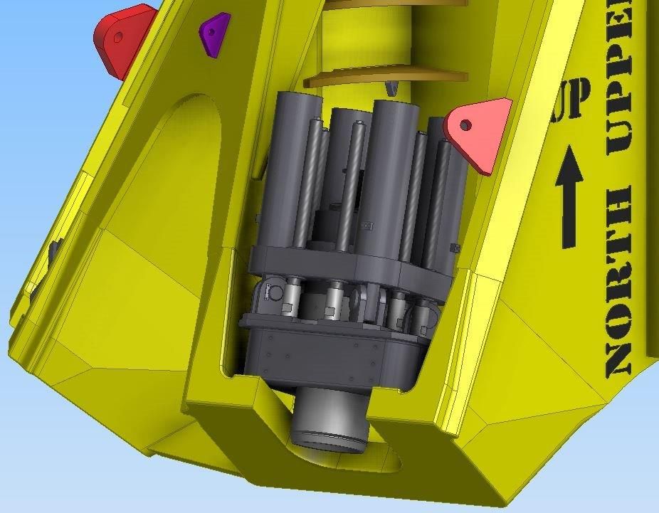
Thanks, purely for info I've attached the GA's of the system as we develop it.

Below is side elevation with section cut away, cylinders extended.

JSinclampangle_zps6cc35c1f.jpg


Iso view, Cylinders retracted

JSIsoAssy3_zpsd6421103.jpg
 
also wondering, just read it through though

My opinion is just .02, but I also doubt the flow divider or multple pumps or any form of open loop synchonization.

But, for a one time use, where synchonization is somewhat loose but it must hold over a long period of time, how about a hybrid thought: If cost and programming and controls is the perceived barrier, use a human controller. Put feedbacks on all four cylinders, digital readouts on a panel, and human operated prop/servo valve with manual pots or sticks? Watch the display and move things slowly in synch. Then sit there intently for 30 minutes and keep them in synch while holding the load.

Not press speed or accuracy, and it only has to work once, but it has to work the first time out the door.
 
Folks

The equipment has now been specified and ordered but had yet to be manufactured, installation is not till May 2014.

The link below is link to the very innovative (IMHO) final circuit design. Its not the easiest to follow but when you’ve lived with it for a while it becomes clearer…

Link

Spec

A five section high pressure piston pump delivers equal fluid to all cylinders, one is used to set the max adjustable pressure and unload the system.

Directional control is via a bank of 4 port high-pressure ball valves connected with a common spindle. Equal and simultaneous operation of the cylinders is ensured regardless of the external load* via cylinder mounted counterbalance valve.

Due to the ATEX environment and long lead (or unavailability) of 500 bar rated explosion proof equipment the electrical content of the system is at a minimum with the control being “mandraulic” operation.


*Recent analysis has suggested rather that seeing the imbalanced load the tensioning system due to is self-weight is likely to sit flush, its self weight wants to fall into the clamp, cancelling out the cable catenary moment which was causing the gap mentioned in previous post above, this simplifies the operation significantly for us.


Hi everyone. Yesterday was my first visit and I am already impressed by the quality of the participants.
escapizm, this is very interesting problem. I would like to ask if you considered using a single hydraulic cylinder instead of four units. Even a hollow piston cylinder of 1,300 metric ton capacity and 1,000 mm stroke is feasible. Do you think there are disadvantages in using just one big cylinder instead of a set of four units?

Your problem is relevant to me because we are working on a project to pull Dyneema rope. We are considering a hollow piston cylinder, our requirements are a bit smaller, so an 800 ton capacity hollow piston cylinder is sufficient, rod diameter is 400 mm. and central hole is 250 mm. We have quotes for that of around GBP 25,000.

I appreciate your feedback, I am a bit surprised you did not choose a single cylinder... Maybe I overlooked something?

Thanks in advance,

Aarne
 
Aarne

We are using 4 cylinders not a single one.

The original solution was to use an annular jack as you suggest with a hole in the centre, I changed it when I joined the team as I had little confidence it, we invented this machine!!!.

The proposed unit had a 50mm stroke and required multiple “re-sets” with mechanical spacer rings being inserted.

However the main concern was as the unit had to have a hole in the centre approx. 700mm in diameter to accommodate our cable and it was VERY sensitive to angular misalignment. As you can appreciate if one side moves out of sync with the other the “circle” becomes and “oval” and in workshop perfect environments we had failures of the seals and that was when we were attempting to test lift true and square vertically. Offshore we are at approx. 36 degree with the addition of a moment caused by the slack catenary of our cable.

The other issue was as you approached the 50mm stroke you had to stop as unlike a normal hydraulic cylinder nothing retained the "piston" on the annular gap and it could pop out !

If your cable is small in diameter and vertical you should be ok.

Your solution is approx. 40 times cheaper than ours! But we do have six machines.

escapizm
 
Status
Not open for further replies.

Part and Inventory Search

Sponsor