Continue to Site

Eng-Tips is the largest engineering community on the Internet

Intelligent Work Forums for Engineering Professionals

  • Congratulations KootK on being selected by the Eng-Tips community for having the most helpful posts in the forums last week. Way to Go!

Complex joint accentricity assumptions correct? 4

Status
Not open for further replies.

NL4L1F3

Mechanical
Mar 9, 2018
30
I am still learning about connection design and everything will be checked by a senior constructor but i have some questions regarding eccentricity's.

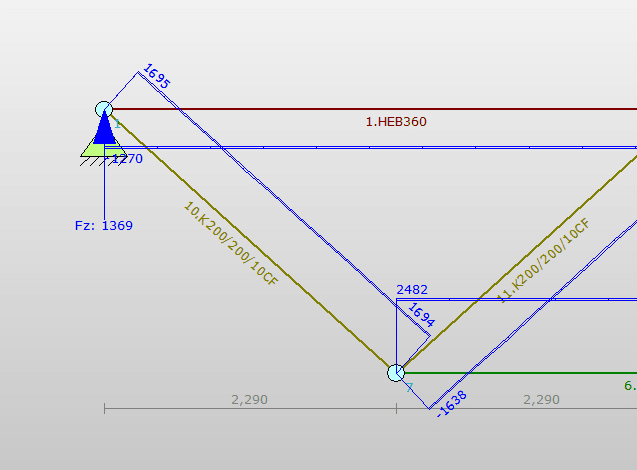
It is about the following joint:
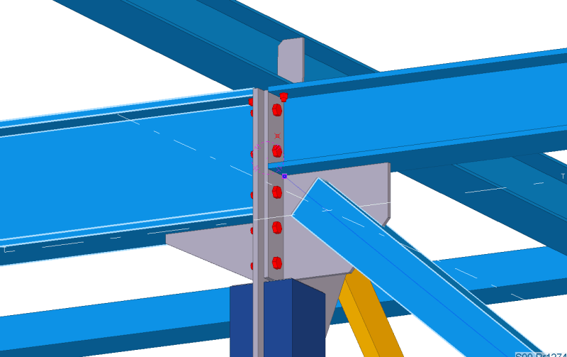
1_t2vzzx.png


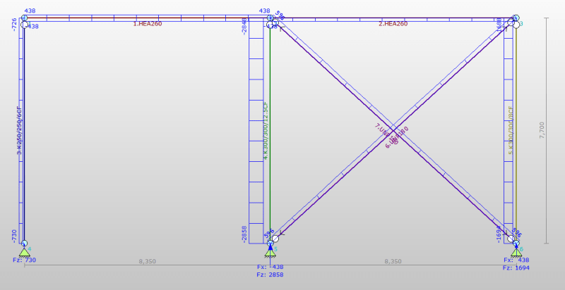
With the following normal forces:
TS1_sjiotj.png


The diagonal is eccentric towards the upper beam of the truss. This will result in a moment of the horizontal component of the 1700 kN.
So the resulting moment is: 1270*0,18=230kNm

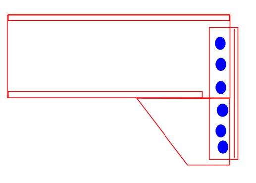
If i test the truss to take this moment like this, (and the UC is ok):
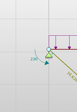
added_moment_because_of_the_eccentricity_ezfs7l.png


then the moment will be taken by the girder and not the connection?
So like this if i input the forces to FEM software (note that the moment is the opposite direction because this is the internal load of the truss?):
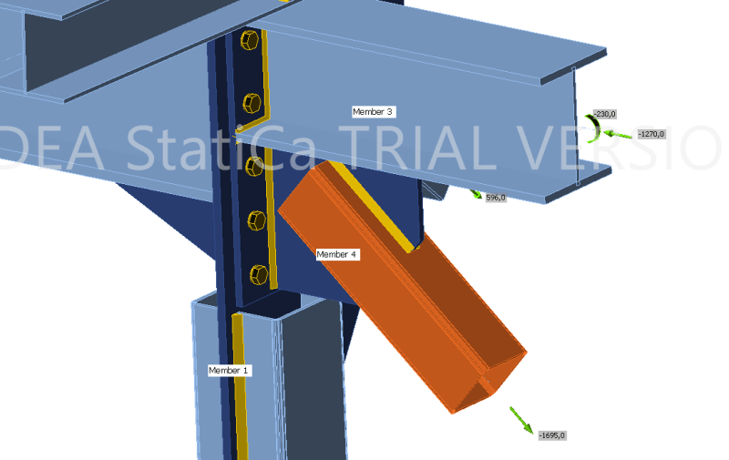
5_uof9bu.png


And then i have the same question about the other diagonal thats connected to this joint. Will moment created by the horizontal_load*(height_beam/2) be taken by the upperbeam as an extra moment or will this also go to the connection below? I wil probably move the point up because the plate below is quite stiff in this direction so my feeling is that a bunch of the moment will also add stress to the plate?
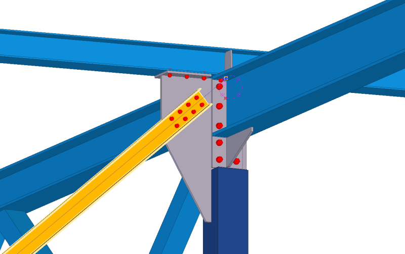
2_okeutd.png


And the result of moving the connecting point up means that the moment goes to the connection where i bolt the beam to the plate?

Thanks in advance :)
 
Replies continue below

Recommended for you

Does it have to be eccentric? Better off making them concentric.
 
The person that is teaching me prefers the location of the diagonal like this because then the connection is more compact and the welds of the plate that connects member4 are loaded with just shear force and no moments.

I will move the UNP up as there is no reason not to. Its more about the principle.
 
It looks a bit bizarre but overall the connection looks 'OK'. The vertical plate coming up from the HSS looks a little thin for me. Upping the thickness would given a much more warm and fuzzy feeling about that connection. My comments are based completely on gut feeling rather than any consideration of the forces or members involved.
 
IMO, it is not a good idea to develop moment connections for the trusses and seems these are BAD details.. I will suggest , extent the HSS to the top and make shear connections with double angle web cleats , fin plates to the HSS.. the work points for each conn. shall match with the analysis model ..

I write ( GOOD AND BAD DETAILING pdf ) and searched the web... one of the outcomes, IMO, which makes sense ;

 
Working on the engineering decision of the connection is an art work.
Beam connections and bracings around the column need to be considered as a whole in case there is no other seperate working condition by separating one or two beams with bracing.

Some cases you cannot get away from eccentricity, however the moments due to axial loads created by the bracing will be shared by the connected members through the components at the connection.
Sometimes the shared moment can be acting against the moments created by the gravity loads. In your case this happens. But if the connected beams to be uniformly lifted by wind suction you need to be carefull, and calculate and size the beam adequately.

Another point is the use of pin connections in the analysis. Local detail shows that the connection is almost fixed by the beam connections on to the column. Your load diagram shows pin. You need to feel about the behaviour of the connected components under actions.

Hope it helps.
 
HTURKAK said:
IMO, it is not a good idea to develop moment connections for the trusses and seems these are BAD details.. I will suggest , extent the HSS to the top and make shear connections with double angle web cleats , fin plates to the HSS.. the work points for each conn. shall match with the analysis model ..

I write ( GOOD AND BAD DETAILING pdf ) and searched the web... one of the outcomes, IMO, which makes sense ;
Except then this creates a different connection.

What you propose would be a pinned connections all round. Yet what is drawn is a moment connection between the beams. Sure your proposal might be simpler. But I would presume that the engineer wanted a moment connection between the beams for a reason.

If my assumption isn't the case then I absolutely agree with your.
 

It is supposed to be a pinned connection. But the load is high. Just for the shearforce i need atleast 8 M30 bolts. So there is no room for that kind of detail? And if the connection is brought out the bolts need to take an extra moment in the connection.

I just started out and this is the detail that is most used in my company for high loaded trusses. I havent seen any trusses connected with fin plates and double angle web cleats connections.
 
OP said:
But the load is high. Just for the shearforce i need atleast 8 M30 bolts.
But that's expected, right? You're transferring a complex set of reaction (Vx, Vy and T) to column from three spans through one single connection plate.
 

The second picture shows that the truss modelled and analyzed with assumption of simple support and the outcome element forces will be compression for top chord (HEB 360 ) and tension for diagonal element K200/200 ( I assume box 200 mm X 200 mm)..

With the proposed connection detail by OP, the top chord will experience (tension + bending) and diagonal will experience ( compression + bending. )

IMO, the moment connection of a truss from ( top chord + diagonal ) is not acceptable.. The moment connection for truss should be with simple connections with top chord and bottom chord ..

If OP posts the full plan , we may see the other supports and our posts could be more helpful..
 
From the figures, I see reactions from 2 trusses and one beam transferring to the colunn through one plate.
 

The column with beam and wind diagonal. The column in question is the middle one:
column_fm9nlv.png


Normal forces of the truss:
Normalforces_xbyq3f.png


moments of the truss:
Moments_vba0ya.png


Moment and reaction force of HEB550 (533 kN)
HEB550_moment_fypcd9.png
 
I've seen it done this way although I'll confess that I've never much liked the look of it myself.

C01_n4thca.jpg
 
I would tend to gravitate toward this type of connection style first (see attached). If you have any axial load transferring to the deeper beam that opposes the smaller beam, a moment will be created between the workpoints. I'd want to ensure this moment stays within the bounds of the HSS, not a flimsy knife plate slotted into an HSS. I'd analyze this as a simple UFM problem w/ the HSS being the "UFM beam" and the beams as the "UFM columns". The horizontal plates would be designed as end plates.

I didn't draw the braces because I'm in a hurry. Sorry I don't have more time to elaborate, being very busy these, but I hope this helps in some way.
 
 https://files.engineering.com/getfile.aspx?folder=98baa58f-90e4-45f7-8e8a-dcc4df7994e8&file=ENGTips_HSS_Complex.pdf

The bracing elements are 2X UNP 160 (and yellow colored at 5th picture yellow colored is that true) ? Are the HEA beams horizontal struts?

If this is true, the work point SHALL be intersection of centerlines of box column+ bracing + and HEA 260 struts...That is, you are expected to extend the column to the top !!

I will suggest you to look to the doc. and develop accordingly..

 
OP said:
If i test the truss to take this moment like this, (and the UC is ok)

First, back to the basics of steel connection design. When we design steel connections, the concept is usually this:

1) We assume a load distribution that satisfies equilibrium.

2) We try to respect stiffness but accept that our assumed load distributions through our connects are not the natural / elastic distributions.

3) We're accept [#2] so long as no brittle failure(s) would occur as the connection load path shifts from its natural / elastic distribution to our assumed distribution (plastic design).

Now back to your particular problem:

4) You have a connection moment that needs to go someplace to satisfy equilibrium [#1]. I feel that it is completely rational to do as you suggested and design the truss top chord and braced frame beam to resolve that moment. That is what I would do and what I've seen others do often in the past. This check on the top chord / beam is part of the connection design since it is necessary to complete the equilibrium load path asssumed.

5) As you and saplanti have intimated, the connection moment will be shared among the members framing into the joint. However, that will occur in a manner that will be quite difficult to predict accurately given the realties of connection flexibility etc. I feel that the rational approach here is to revisit the design of each member coming into the joint making a conservative assumption about how much moment that member may see. This is one of the reasons why it is desirable to detail connections such that the connectivity between the members coming into a joint is limited to that which is truly necessary. Making a conservative estimate of the moment going into all of the members in a joint like this can start to get costly, both in terms of your design effort and in terms of the fabrication costs.

For this connection, I don't love that all of the load is coming into the column through that single knife plate. Per the stuff mentioned above, the plate will see axial stress, in plane bending stress, and out of plane bending stress. And it will experience those things to degrees that will be difficult for you to predict. Will that cause yielding on on the compression edge of the plate? It's hard to say without designing the plate very conservatively. On intuitive level, I worry that mission critical plate might buckle. That said, I acknowledge that the connection is detailed such that it affords a healthy amount of bracing to the plate.
 
DrZoidberWoop said:
I would tend to gravitate toward this type of connection style first (see attached). If you have any axial load transferring to the deeper beam that opposes the smaller beam, a moment will be created between the workpoints. I'd want to ensure this moment stays within the bounds of the HSS, not a flimsy knife plate slotted into an HSS. I'd analyze this as a simple UFM problem w/ the HSS being the "UFM beam" and the beams as the "UFM columns". The horizontal plates would be designed as end plates.

I didn't draw the braces because I'm in a hurry. Sorry I don't have more time to elaborate, being very busy these, but I hope this helps in some way.

Thanks for the detailing example! There are no normal forces between the 2 beams. the normal forces of the truss are all internal.

I also looked up UFM. Thats definitly something I have to look at more closely.

But now the diagonal of the truss is hanging freely untill it is bolted to the gusset plate?

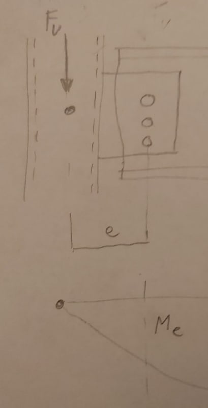
And something that was teached to me is the following but i am not sure if this is true anymore?:

The main wireframe calculation calculated the following, with the added moment graph (example with one beam):
a59695cd-58c9-43a4-93e4-d351f7e96e81_rzxuj7.jpg


To move the force to the bolts that means i have to introduce an extra moment like this on top of the connection right:
eb6dc5aa-e9ec-48d0-901d-b8dd463a0f3e_hftghp.jpg


This creates a pretty big moment that cant be taken by the bolts. This was the reason for us to move the connection to the center of the column with the knife plate.

If we dont take this moment into consideration like this that that means the column needs to create the extra moment instead right?
 

Thanks for the detailed answer. But to make sure i understand correctly (english not my main language)

The connection moment talked about in (#4) is the moment induced by the eccentric diagonal. And is applied to the beam to check it. In reality the force goes to all components related to the stiffness of each component/connection. This is why a creating a pinned connection is important. That means i can predict the forces better. When the beam is connected with a simple connection that would almost force the eccentricity to go to the upper beam of the truss?
 
The bracing element is a UNP180 and is indeed the yellow element. And the HEA beams introduce the force to the UNP's. I have moved the centerlines to allign with eachother.

One thing that wasnt clear to me is the following:
HTURKAK said:
That is, you are expected to extend the column to the top !!

Why is it expected to move the column to the top?

And sadly the link did not work.
 
Exactly right except, perhaps, with less emphasis on the importance of creating a pinned connection. I would say that doing so is certainly desirable, but by no means mandatory.

My preferred version of this detail actually does not run the column all the way to the top. I find that there is often advantage in running the truss connection over top of the columns. Big girder trusses deliver big loads and those can cause issues with connection design and column capacity where the load would be delivered to the side, more eccentrically. Detailing similar to what's shown below is fairly common in North American, industrial, joist girder building. Obviously, all of the things that would require torsional bracing would receive it.

C01_labhoh.jpg
 
Status
Not open for further replies.

Part and Inventory Search

Sponsor