Continue to Site

Eng-Tips is the largest engineering community on the Internet

Intelligent Work Forums for Engineering Professionals

  • Congratulations KootK on being selected by the Eng-Tips community for having the most helpful posts in the forums last week. Way to Go!

Complex joint accentricity assumptions correct? 4

Status
Not open for further replies.

NL4L1F3

Mechanical
Mar 9, 2018
30
I am still learning about connection design and everything will be checked by a senior constructor but i have some questions regarding eccentricity's.

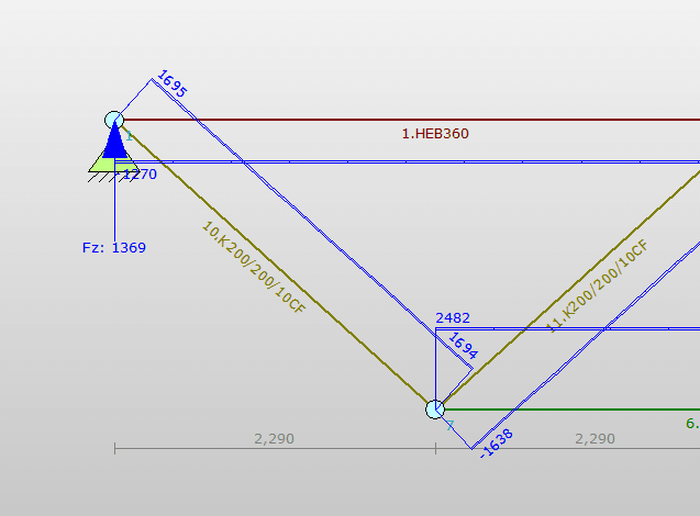
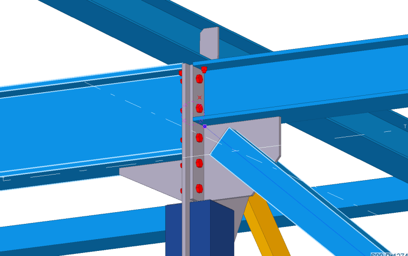
It is about the following joint:
1_t2vzzx.png


With the following normal forces:
TS1_sjiotj.png


The diagonal is eccentric towards the upper beam of the truss. This will result in a moment of the horizontal component of the 1700 kN.
So the resulting moment is: 1270*0,18=230kNm

If i test the truss to take this moment like this, (and the UC is ok):
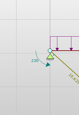
added_moment_because_of_the_eccentricity_ezfs7l.png


then the moment will be taken by the girder and not the connection?
So like this if i input the forces to FEM software (note that the moment is the opposite direction because this is the internal load of the truss?):
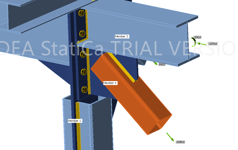
5_uof9bu.png


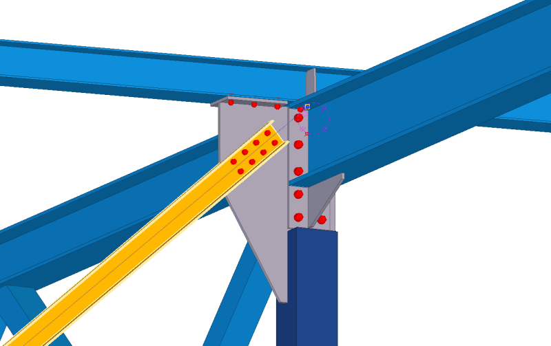
And then i have the same question about the other diagonal thats connected to this joint. Will moment created by the horizontal_load*(height_beam/2) be taken by the upperbeam as an extra moment or will this also go to the connection below? I wil probably move the point up because the plate below is quite stiff in this direction so my feeling is that a bunch of the moment will also add stress to the plate?
2_okeutd.png


And the result of moving the connecting point up means that the moment goes to the connection where i bolt the beam to the plate?

Thanks in advance :)
 
Replies continue below

Recommended for you

KootK said:
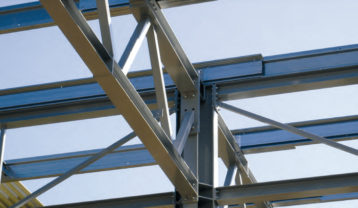
My preferred version of this detail actually does not run the column all the way to the top. I find that there is often advantage in running the truss connection over top of the columns. Big girder trusses deliver big loads and those can cause issues with connection design and column capacity where the load would be delivered to the side, more eccentrically. Detailing similar to what's shown below is fairly common in North American, industrial, joist girder building. Obviously, all of the things that would require torsional bracing would receive it.

I really like this design. Tommorow i am going to try to recreate it.

The beam were the frame brace is connected to will now be loaded with an extra moment like discussed before. Would it be better to move this point up to the middle of the beam or is this actually the location that you prefer?
 
NL41F3 said:
Would it be better to move this point up to the middle of the beam or is this actually the location that you prefer?

It's actually the location that I prefer for this specific detailing situation.

NLF1# said:
The person that is teaching me prefers the location of the diagonal like this because then the connection is more compact and the welds of the plate that connects member4 are loaded with just shear force and no moments.

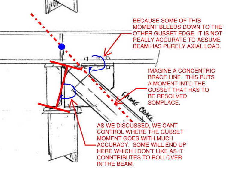
I agree with your mentor in that regard. I gotta choose my words carefully here or, the next thing that I know, I'll have folks crawling all over me thinking that I don't understand why concentricity is a good thing. Concentricity is a good thing in general and, all else being equal, it should be strived for. That said, "all else" is often not equal and when that is the case, I feel that a more nuanced approach is sometimes justified.

A prime example where perfect concentricity is detrimental is the detailing of braced timber frame joints. You'll see a lot of engineers detailing those concentrically because they were taught "that's what's right". Unfortunately, it produces the condition that you mentioned where the gusset plates have in plane bending in them. And that means that the fasteners to the wood induce perpendicular to grain tension in the members which is, of course, the exact opposite of skillful detailing.
 
KootK said:
It's actually the location that I prefer for this specific detailing situation.

The reason is that the connection then has pure shear force and no moments? (because you have no bolts in the truss upper beam?
 
1) The shear only gusset tends to be compact and economical as your mentor mentioned and;

2) The engineering reasons mentioned below.

C01_w6hh3r.jpg
 

I really appreciate the answers you are giving [glasses]
 
You're most welcome. Do pay it forward by returning here to help out with future steel detailing questions. We'd welcome the help.
 
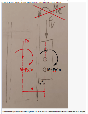
The big moment is on the column.

image_s34d4m.png
 

I thought so already. But this is what my mentor tought me. We only make the details and not the main calculations. In the main calculation the beam is simply suppported at the center of the profile and no moments are taken in consideration. That is why we see the connection as part of the beam. This also results in compression at the top of the connection what seemed counter intuiitive.

But if this is wrong then how should we otherwise deal with the situation? If we look at the moment line of the beam that is connected to the center of the column. We add a moment to the beam and column at the start so the resulting moment is 0 at the point of the bolts?

And how does one explain this to his mentor that has done this this way for 30 years [rednose] any literature that explains this better? Would be helpfull for me aswell
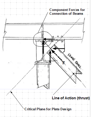
 
Concerning reaction from the diagonal brace (moment not shown).

image_dtfmkt.png
 
Show him the diagram. I didn't read the entire thread, thus may have missed something. But note that even there is moment in the connection and in the column, the beam itself is still is simply connected due to the flexibility of the knife plate and the bolt connection. However, I believe AISC ignores the small moment in the connection though.
 

I will try to respond to your questions which are explicitly mentioning my nickname ;

The best analysis is the model that reflects the real structure.... In your case, the analysis model is based on pin connections and the columns ,beams and bracing elements has connections at a single point without eccentricity..

In this case, you have two options;

- Follow the analysis model and provide the connections reflecting the analysis..which I have suggested,
- Make the truss connection ' seat type ' as proposed by some commenters and ask to the designer to adopt his model considering the level changes, eccentricities, torsional stifnesses etc and re-run the analysis for the final situation ....

My region is at western side of Pacific.. ' All Quite on Western Front..' .. The analysis performed by SE, the shop drawings sometimes by manufacturer.. The analysis performed with a program say SAP 2000, shop dwgs with XSTEEL etc...

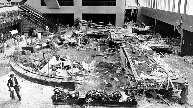
If the designer is a different group , detailer and manufacturers are different groups and the person tasked for connection details asks basic questions in a forum ,I searched the web and one of the possible outcomes ;Hyatt Regency Walkway


hyatt_regency_kansas_hyzlok.jpg


I suggested you to look to the doc. If the link does not work , i uploaded the doc.

If I were in your shoes, I would try to learn the basic concepts from the book to make my mind ( Handbook of Structural Steel Connection Design and Details by Akbar R. Tamboli ) ,I would delete the box columns, use UC or HEM and strong axis parallel to truss , and choose rigid connected trussed beams :

trussed_beams_myfbde.png


Yes i know. I am still a student. Everything will be checked by someone more expierenced. I want to come up with a better solution.
 
NL4L43 said:
Yes i know. I am still a student. Everything will be checked by someone more experienced. I want to come up with a better solution.

To your credit, I've seen far worse proposals on connections posted on this site from far more 'experienced' people. Steel connection design can get very complicated very quickly when there is a deviance from a simple shear connection. Honestly it does boggle my mind that connection design in some localities is often separated from general structural design.

The key question you should be asking yourself every step of the way is what assumptions were made during the structure design. Particularly regarding pinned vs moment connection, and to a lesser extent eccentricity. You then need to try to match those assumptions as closely as possible or refer it back to the design engineer.


Oh and plenty of us on this site are still learning. We get a bunch of inexperienced just asking for a free help. But there are also a bunch of highly experienced people. I'd put myself in the category of 'still learning' and 'plenty more to learn'. After all, what sort of engineer would I be if I was closed minded to improving my trade?
 
human909 said:
To your credit, I've seen far worse proposals on connections posted on this site from far more 'experienced' people. Steel connection design can get very complicated very quickly when there is a deviance from a simple shear connection. Honestly it does boggle my mind that connection design in some localities is often separated from general structural design.

The key question you should be asking yourself every step of the way is what assumptions were made during the structure design. Particularly regarding pinned vs moment connection, and to a lesser extent eccentricity. You then need to try to match those assumptions as closely as possible or refer it back to the design engineer.

Thank you. I still have a lot to learn.

I have talked about my mentor about the issues we have discussed here and he says that yes everyone in this thread is correct. But as you said we do not make the general structural design. And the people that do ,do not consider moments in the column to create a simple connection. That is why he assumes that the pin is inside the column even tho this is not correct. Because this is the hand that was dealt to us.

When i get a project i will talk to the head designer and discuss the options with him to get to a better solution.
 
Status
Not open for further replies.

Part and Inventory Search

Sponsor