Eng-Tips is the largest engineering community on the Internet

Intelligent Work Forums for Engineering Professionals

Composite Arch Construction Stage Analysis

Status
Not open for further replies.

netsonicyxf

Structural
Feb 19, 2010
49
0
0
US
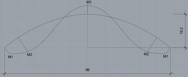
The arch has 96m in span and 19.2m in rise. It has pin support at both ends and is made of steel and concrete.
It has 3 Construction Stages
1. field installation of steel tube
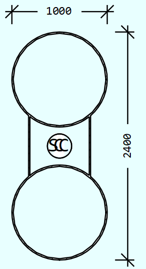
1_nqee1p.png

2. put concrete in the bottom steel tube
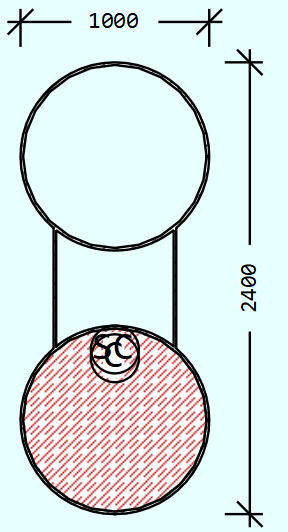
1_obwmny.png

3. put concrete in the top steel tube
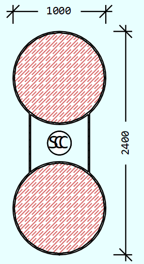
1_spmn84.png


We use Midas Civil, RM Bridge (TDV) and Sofistik to do the construction stage analysis
We will consider time effects, such as creep, shrinkage and E module increasing with time in the furture. But for now, the model is under self-weight only, no time effects.
The boundary conditions are the same for all 3 softwares in all 3 stages, the support is at geometry center of the whole steel tube as shown in the stage 1.
For Midas, we use NonLinear analysis considering Accumulated Stage
Geometric nonlinear analysis is carried out with accumulated effects of the models of each construction stage. This option is used for the forward analysis of a cable stayed bridge considering large displacement.
For RM Bridge, we use “Accumulate Stiffness (Stage) Analysis”
The internal force state (normal forces) of previous construction stages is considered in the p-delta effect calculation. The relevant internal force state must be stored in the specified summation load case.
For Sofistik, we use CSM(Construction Stage Module) Line (Linear analysis) and CSM → TH3 (3rd order geometry nonlinear), both gives very similar results

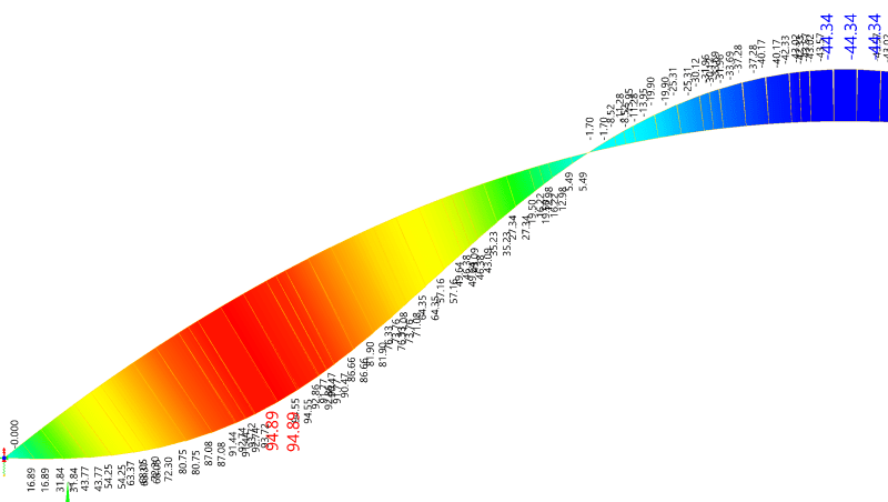
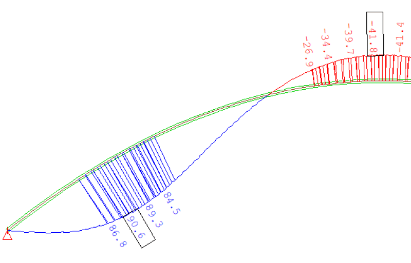
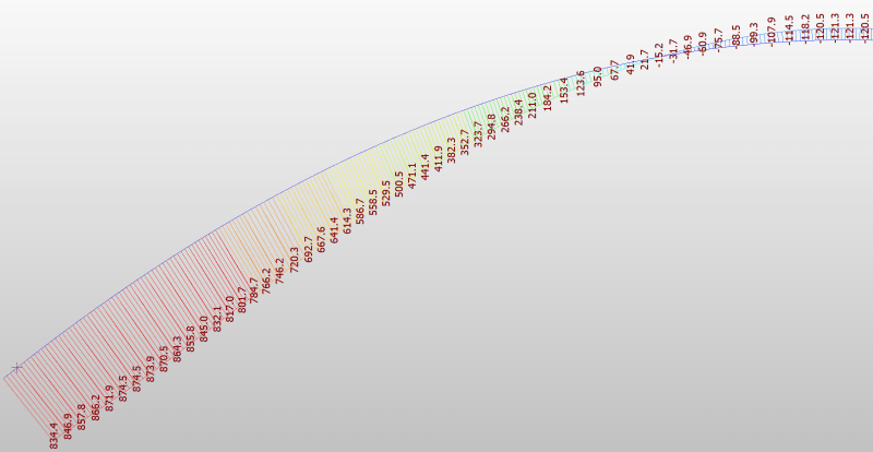
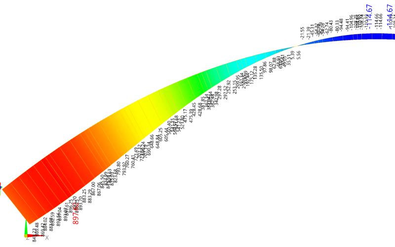
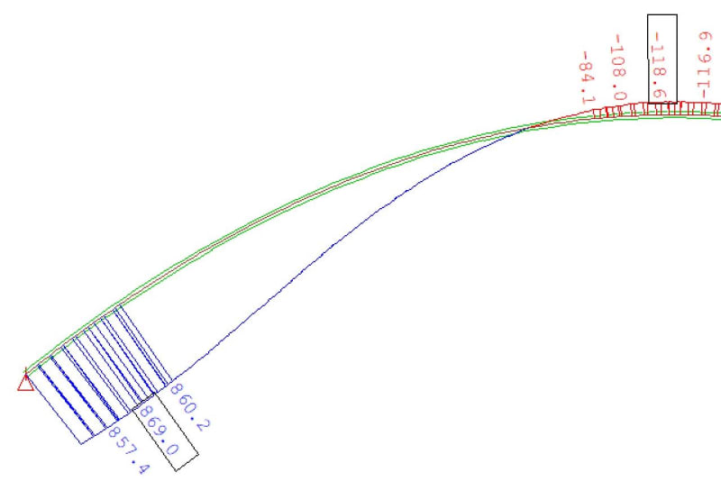
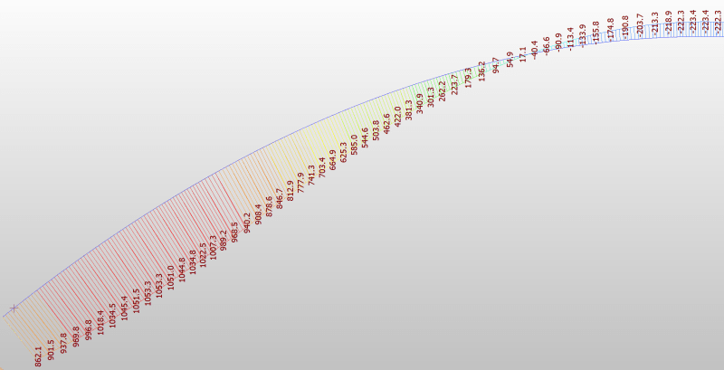
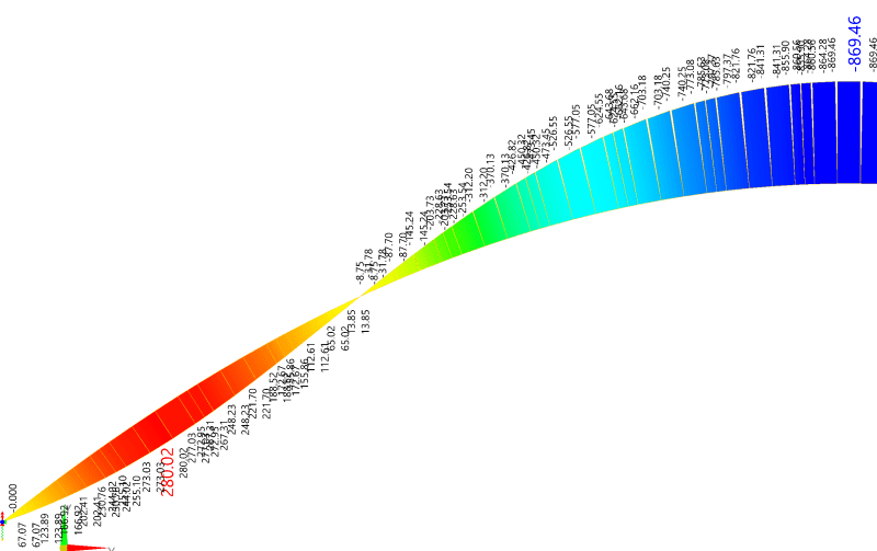
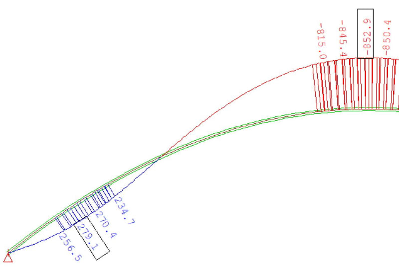
RM Bridge and Sofistik show very similar moments of the arch in all three stages,
while Midas Civil shows similar moments of the arch in the 1st and 2nd stages as those in RM Bridge and Sofistik, but very different moment in the 3rd stage.

Stage 1 (The moment diagram due to self-weight is symmetrical, so only half of it is hown here)
Midas Civil
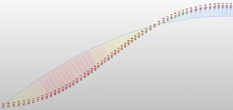
1_ligsrg.png

RM Bridge
1_aomvrm.png

Sofistik
1_e3gwxw.png


Stage 2
Midas Civil
1_nhuttd.png

RM Bridge
1_l8yvib.png

Sofistik
1_fwdnto.jpg


Stage 3
Midas Civil
1_tdhbhu.png

RM Bridge
1_ekqeim.png

Sofistik
1_fhyjud.jpg


1. Which result is correct?
2. If Midas is correct, how to fix it in RM Bridge and Sofistik; if RM Bridge and Sofistik are correct, how to fix it in Midas.
 
Replies continue below

Recommended for you

netsonicyxf - You can take moments about the neutral axis and get a moment at the support if you want to, but it's simpler to take moments about the centre of the steel sections, and since there is a pinned support there the moment will be zero.

Why are you treating the concrete as having full stiffness as soon as it is poured? That's just wrong.

Doug Jenkins
Interactive Design Services
 
I second Doug's suggestion to switch to wet-->dry concrete analysis. You'll have to do it eventually so might as well be now, and then you'll have Doug's results to compare to.
 
IDS said:
Why are you treating the concrete as having full stiffness as soon as it is poured? That's just wrong.
steveh49 said:
I second Doug's suggestion to switch to wet-->dry concrete analysis. You'll have to do it eventually so might as well be now, and then you'll have Doug's results to compare to.

For simplicity, I model the concrete rib as "precast" concrete, so it has both weight and stiffness at the same time.

IDS said:
You can take moments about the neutral axis and get a moment at the support if you want to, but it's simpler to take moments about the centre of the steel sections, and since there is a pinned support there the moment will be zero.
The supports in all 3 stages are fixed at center of steel sections.
In stage 1 & 3, the center of gravity (CG) is the same as the center of steel sections, in Stage 2, CG is below the the center of steel sections.
In construction stage analysis, the support at cross section is fixed, so in Stage 2, it should not be moved to CG. Therefore there should be moment at pin support.


netsonicyxf, if we assume that the concrete is to be poured into the CHS at site in stages 2 and 3, then IDS is correct (and I was wrong earlier as I didn't account for the load path of the concrete in stage 2). The wet concrete weight load in stage 2 can only travel through the steel - with no contributions from concrete stiffness since it is still wet. This will be the case even when the concrete hardens (stresses are now locked-in). Therefore, there should not be any support moments at stage 2 for your given model.

netsonicyxf said:
For simplicity, I model the concrete rib as "precast" concrete, so it has both weight and stiffness at the same time.
Given your staging models, is this a valid assumption ? How will this assumption be realised in practice ? Unless I'm missing something, concrete will inevitably have to be poured as wet concrete into the CHSs. This means that stage 2 support moments will be zero.

I also want to revisit your original query:

netsonicyxf said:
1. Which result is correct?
Are you simply testing the programs to check their results and this isn't really for a project (or it is checking against an already finished project) ? Or is this an actual project you're working on right now ? This is important because I think most of us have been assuming the latter. But if it's the former, then I would say you're allowed to make the 'precast concrete' assumption - but only from a QA testing perspective where we're often required to put in invalid/absurd data to test the programs.

Regardless, it is more realistic to not have any support moments at stage 2 and then to have some support moments at stage 3.

 
I model the wet concrete. It has 5 stages
Stage 1, Steel section
Stage 2, wet concrete in the bottom tube
Stage 3, hard concrete in the bottom tube
Stage 4, wet concrete in the top tube
Stage 5, hard concrete in the top tube
results_summary_wet_concrete_w7vtl5.png


FE_struct1 said:
concrete will inevitably have to be poured as wet concrete into the CHSs. This means that stage 2 support moments will be zero.
As you said, when wet concrete is poured at STG 2, there is no moment at pin support.
But when wet concrete hardens at STG 3 & 4, there are moments at pin supports.
FE_struct1 said:
is this a valid assumption ? How will this assumption be realised in practice ?
That's why I model the concrete as "precast concrete". I know it not a pratical assumption, but modeling wet concrete or not won't change the fact that the moment exists at pin support.
 
Curious results. No change in Midas from stage 4 to 5 (just concrete hardening; no actual change in stress in any element). However the stage 2-3 results do change despite also being just concrete hardening. I'd look for an input error in one or both of those stages.

Stage 5 of the other two programs suggests they just report a support moment equal to the axial force multiplied by the offset of the centroid at the stage in question, but you should check that given we don't know your axial forces. Looks like you need post-processing to understand the actual stresses which defeats the purpose of the staged analysis to some degree. If nonlinear effects are small, separate analyses for each stage and then simply adding the results may be simpler.

Try comparing to Doug's results now you have the same staging.
 
netsonicyxf said:
modeling wet concrete or not won't change the fact that the moment exists at pin support.
I disagree. If the only loads in your models are those from self weights of the elements, then wet concrete weight in the lower CHS will not induce moments. This is because of the locked-in stress effect.

netsonicyxf said:
But when wet concrete hardens at STG 3 & 4, there are moments at pin supports.
We'll need details on how exactly you've modelled the wet concrete to dry concrete behaviour. I'll expand a bit on midas as I've used it before:

In midas, you're required to activate the self weight at some stage. The self weight feature is just a single entry that automatically accounts for any weight changes during staged construction. I'll make a few assumptions about your latest model with 5 stages:
[li]I'm guessing you've activated the self weight feature at stage 1 ? [/li]
[li]I'm also guessing that in stage 2 your wet weight is just a line load on steel ? [/li]
[li]Final guess - this line load is then deleted in stage 3 and gets replaced by the 'precast' concrete self weight? [/li]

If the above guesses are correct, then your model isn't giving the right results - because of the way midas works.

During staged construction analysis, midas will perform a recalculation of stresses for any new loads added in a stage. Sadly, midas does not know (and - to my knowledge, there is no direct way to enforce it) that the line load simulating concrete wet weight in stage 2 and the 'precast' concrete weight in stage 3 are the same load. It treats the 'precast' as a brand new load - and the load path for this brand new load is the composite load path because you've added in a 'precast' concrete with full stiffness.

In reality, unless you've added extra loads in stage 3, there should still be zero support moments at stage 3.

Stage 4 and 5 will have moments in your models if the support location remains at the steel section centroid.

A good way to confirm this is to not use the self weight feature at all but to just apply the self weights as UDL:
[li]Self weight of the steel UDL is applied in stage 1 - No support moments expected[/li]
[li]Wet weight of the bottom CHS concrete UDL is applied in stage 2 - No support moments expected as centroid unchanged[/li]
[li]'Precast' Concrete in bottom CHS is wished in place at stage 3 to simulate hardened concrete. No new loads applied, so no support moments expected[/li]
[li]Wet weight of concrete in upper CHS applied as UDL at stage 4 - support moments expected as Neutral axis has shifted[/li]
[li]'Precast' Concrete in upper CHS is wished in place at stage 5 to simulate hardened concrete. No new loads applied. Support moments should remain the same as in stage 4[/li]

This should give results much more in line with Doug's results.

 
FE_struct1 said:
A good way to confirm this is to not use the self weight feature at all but to just apply the self weights as UDL:
Self weight of the steel UDL is applied in stage 1 - No support moments expected
Wet weight of the bottom CHS concrete UDL is applied in stage 2 - No support moments expected as centroid unchanged
'Precast' Concrete in bottom CHS is wished in place at stage 3 to simulate hardened concrete. No new loads applied, so no support moments expected
Wet weight of concrete in upper CHS applied as UDL at stage 4 - support moments expected as Neutral axis has shifted
'Precast' Concrete in upper CHS is wished in place at stage 5 to simulate hardened concrete. No new loads applied. Support moments should remain the same as in stage 4
I follow you suggestion, replacing the self-weight with line load. The results from Midas are almost the same as before.

FE_struct1 said:
In reality, unless you've added extra loads in stage 3, there should still be zero support moments at stage 3.
There is no extra load in stage 3. But since concrete is hardened in this stage, the neutral axis is NOT at support.
For Midas Civil
If I use Geometry Linear & Accumulative Stage Analysis, there is no moment at support in stage 3;
but if I use Geometry Nonlinear & Accumulative Stage Analysis, there is moment at support in stage 3.
results_summary_wet_concrete_iyig3b.png

I didn't show geometry linear analysis results of RM Bridge and Sofistik, because the difference between linear analysis results and nonlinear analysis results are minimum.
 
IDS said:
In summary:
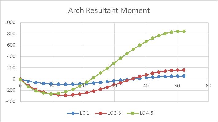
The LC 1 results are reasonably close to the results in the OP.
LC 2 should not have any moment at the support because the load is applied as wet concrete.
LC 3 results are the same as LC 2 because it models the hardening of the concrete, ignoring shrinkage.
My LC 4 results have no moment at the supports, because I have taken moments about the centre line of the steel section, but if you insist on using moments about the section centroid there should be a moment at the supports because the lower tube is filled with hardened concrete and the upper tube isn't.
LC 5 is the same as LC 4 because it only models the hardening of the concrete in the upper tube.
Hi Doug, FE_struct1 and I both think there should be moment at support in stage 4, because the support location remains at the steel section centroid.


steveh49 said:
Looks like you need post-processing to understand the actual stresses which defeats the purpose of the staged analysis to some degree.
Thanks for the suggestion. I will try to compare the stresses from different softwares.

steveh49 said:
Curious results. No change in Midas from stage 4 to 5. Try comparing to Doug's results now you have the same staging.
The geometry linear analysis results from Midas (and Autodesk Structural Bridge Design) shows no change from stage 2 to 3 and from stage 4 to 5, which is the same as that in Doug's "morphed" result
TubeArchMom_qo4kdd_qrrla9.jpg
 
Findings:
1. Sofistik and RM Bridge have very similar results of internal forces in all the stages,
2. Midas Civil has very similar results of internal forces as those from Sofistik and RM Bridge in all the stages except the last stage.
3. The stress results from Sofistik and RM Bridge are very similar. Unfortunately, Midas can’t give me stress results for user-defined composite cross section in construction stage analysis.

The moment at pin support at stage 2 is due to the rigid link between support and neutral axis, because the neutral axis moves downwards.
BUT at stage 3, the neutral axis moves back, there is NO rigid link between support and neutral axis. Therefore there should be no moment at pin support.
The Sofistik and RM Bridge results are correct by the above qualitative analysis, while the non-zero moment at pin support at stage 3 shown in Midas Civil is wrong.


Status
Not open for further replies.
Back
Top