Continue to Site

Eng-Tips is the largest engineering community on the Internet

Intelligent Work Forums for Engineering Professionals

  • Congratulations SSS148 on being selected by the Eng-Tips community for having the most helpful posts in the forums last week. Way to Go!

Composite Girder Analysis using Rigid Links in RISA 3D or Other Programs (Bridge)

Status
Not open for further replies.

mjungco

Structural
Apr 21, 2014
7
Hi Everybody,
I am using RISA-3D for some bridge analysis, and I am having some difficulty with modeling composite behavior. I realize that RISA does not natively support composite analysis, but I am trying to find a way to make it work using rigid offsets to connect my deck elements (plates) to my beam elements.

I am designing a bridge with curved girders, and girder spacing that varies across the span. Because of the complex geometry of the framing plan, I would like to model the deck elements seperately from the girder elements using plates that change in width rather than having to put in a bunch of unique beam elements with different composite section properties all over the bridge.

I would also prefer the deck elements be separate so that I can use them to distribute loads across the deck to the different girder elements, as I need to account for the torsion on my curved members, and cannot just use AASHTO distribution factors.

I have started off by modeling a simple span beam with a point load in order to ensure that the program is behaving the way I expect. I am able to match the moments and shear with my hand calcs (The model results in bending in both the beam elements and the deck elements, along with an axial force couple in the 2 elements that resolve to the expected total moment), however I cannot match RISA's stress distribution in the beam elements. The value I am most interested in is the stress at the bottom flange, and this model is approximately 3% off from what it should be.

RISA_Simple_Span_mw2ttm.jpg
RISA_Cross-Section_lkf3pj.jpg

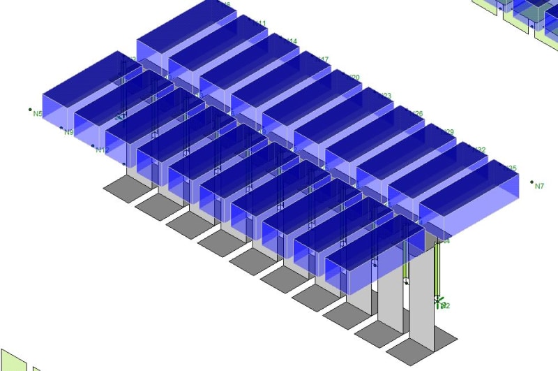
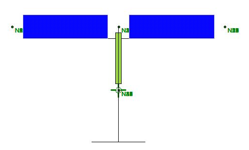
Here's the simple span model. I have 8" concrete plate elements (blue) connected to Tapered WF steel elements (Grey) with Rigid Offset elements (Green).

It's important that I can trust the stress values because the final geometry of the bridge will be pretty complex, and will make it extremely difficult to resolve member forces and calculate stress by hand.

I am wondering if anybody has had any luck using rigid offsets to create composite members in RISA. If so, what value did you use for rigid offset length (I have tried N.A. distance, COG distance, and 1/2 depth; and none have produced correct values)?

If nobody has had luck in RISA, I would ask if anybody has had better luck modeling composite behavior in a different program such as SAP2000, or CSI Bridge, that are in the ballpark of RISA in terms of cost.

Thanks for reading. Any help would be greatly appreciated.
 
Replies continue below

Recommended for you

You may have seen this already, but check out Link, specifically the "Modelling Composite Behavior" section, it describes what length to use for your rigid links.
 
mJungco said:
I realize that RISA does not natively support composite analysis, but I am trying to find a way to make it work using rigid offsets to connect my deck elements (plates) to my beam elements....

...The value I am most interested in is the stress at the bottom flange, and this model is approximately 3% off from what it should be.

First, I'll point out that RISA-3D doesn't natively support composite beams. But, RISAFloor does. Granted RISAFloor won't do curved beams, so it won't help you here. But, I wanted to properly identify the limits of the various RISA programs.

Finally, it's tough for me to know what's causing the difference between your analysis and hand calc numbers. However, if you're within 3% of the stress number, I'd say you're actually doing very well.

In the past, I have compared RISA-3D analyses like the to RISAFloor composite beam calculations. What I tended to find was the following:
a) I had to be careful with how I modeled that slab, or else the beam started to behave as if it wasn't simply supported in RISA-3D.
b) The deflection tended to match up pretty well for a 100% composite beam. But, tended to be too stiff (in RISA-3D) for partial composite cases.
c) I didn't tend to use stress checks in RISA-3D. Although I think the total force and moment in the section should still be pretty good at every spot along the length of the beam. After all, everything still has to obey statics.
 
Thanks Shotzie. I think I read that section initially, but I must not have caught the section where it explicitly states the rigid link connection points. That takes the mystery out of my rigid link length.
 
For the neutral axis location, are you using the elastic NA of the bare steel beam or the elastic NA of the transformed section?
 
Thanks JoshPlum.

I had seen the bit about RISAFloor doing composite, but as you noted, it has its own limitations.

Like you said, 3% isn't too far off for stress. But my concern is, if I'm 3% off for such a simple load case (point load on a simple span beam), then I'm not sure what level of confidence I can have when I start introducing more complex loadings like torsion, etc. I am just trying to determine if this 3% is due to an issue with the way I'm modeling, or something more inherent to the program, or if there is some behavior that I'm overlooking. It sounds like you have not found RISA's member stresses for composite behavior to be super-accurate in the past?

I agree with you that the moments and other global load effects should be pretty accurate, as the program will have to satisfy equilibrium, but because the final geometry of my structure is going to create challenges with resolving these force effects in a straight-forward way, I was really hoping to rely on the member stresses output for my design.
 
Hi Bones206.
I tried based on the neutral axis of the non-composite steel section. (I think I also tried the composite neutral axis, which made it worse).

Based on that link that Shotzie provided, it looks like the rigid link length should be from the 1/2 depth of the beam to the 1/2 depth of the deck. This is what gave me the most accurate stress distribution (still off by 3%). This also produced the most accurate graphic in RISA when I rendered it, the bottom of the deck element lies right at the top of the flange.

I also created a separate model with the beam modeled as a generic blob element, and the rigid link was based on the distance from the neutral axis of the blob to the middle of the deck element. This approach was more accurate for bending stress than using the Tapered WF member, but I'm worried it will have it's own issues when it comes to torsional stress because it doesn't know how the material is distributed.

EDIT
Actually, I looked back at my results. The rigid link from the neutral axis gave me the most accurate result for bottom flange stress (3%). When I took the rigid link from the half-depth, I was off by 5% on the bottom flange stress. One other concern is, none of these seem to be very accurate with the top flange stress.

Sorry, I've modeled this so many different ways, it's hard to keep track.

 
I don’t think half the depth would apply here, since your beam is not symmetric about the NA. Just to be clear, when you try the NA approach, is the total length of the rigid link = (distance from NA to top fiber) + (half the slab thickness) ?
 
@Bones206
Yes. I used Distance from NA to top fiber + deck thickness / 2.
That seemed to work for the generic "blob" element, because the section is defined by the neutral axis location. And when you model the element, it shows it rendered at the neutral axis.

However, with the Tapered WF section, which I would prefer to use, it models the section at the mid-height regardless of N.A. location (as can be seen in the screenshots above). So, if I set the rigid link length based on the N.A. location, there is a gap between the top flange and the bottom of the deck.

The program knows where the N.A. is, and seems to handle bending in the section correctly (when I model just the beam element, I get the theoretical values I expect). I think the main crux of the issue is how the program distributes the axial force couple between the deck and the girder.
 
Just an update on this modeling issue.

I believe the discrepancy I've seen in the girder stresses stems from the transverse flexibility of the plate elements. Where composite beam design assumes the plates essentially stay fully rigid transversely, and act just like a girder flange, the plate elements are allowed to bend along the axis parallel to the girder line to create a concave deflected shape.

When I looked at the deck stresses, I was able to confirm that there are greater stresses at the nodes directly over the girders than at the nodes on the outside edges of the plate elements. When I replaced the plate elements in the deck with wide beam elements (which only bend in one direction), I got stresses closer to what I expected (especially the top flange value), but still off by ~3%.

I don't think using beam elements is going to work for modeling my bridge, but at least I have determined a plausible explanation for the behavior I was seeing.
 
You could try changing your mesh size to see how it affects your results. If you double the number of elements, do you see a reduction in that 3% "error"? Also, try sub meshing the plates until you have a more square aspect ratio and see if that has any effect on the results. Basically, try to see if there is a trend towards convergence to the theoretical value as you refine the model. If it stays at 3%, then at least you can rule out meshing as a factor.


In your beam and plate model the beam and plate elements should definitely be placed at the centroid of the members they represent.

As stated in your last post, the beam and plate model will give different results to modelling the composite member as a single beam, because the latter assumes plane sections remain plane, but I don't see this as a reason to reject the use of the beam and plate model. It is modelling the behaviour of the actual structure more accurately than the simple model, so why not use it?

Doug Jenkins
Interactive Design Services
 
In RISA you can disable shear deformations in the Settings -> Solutions tab. Would that change your results to be closer to the hand calculation values? See this thread as well for some discussion on that topic Link. I haven't thought enough about whether shear deformations would impact stress results in RISA to comment further on that.
 
The shear deformation setting should only affect member deflections, I believe, not the plate elements. The shear deformation is too much of a fundamental portion of the plate element formulation to be able to turn off so easily.
 
The shear deformation setting should only affect member deflections, I believe, not the plate elements. The shear deformation is too much of a fundamental portion of the plate element formulation to be able to turn off so easily.

... and it is the shear deflection in the plates that is causing the "problem".

If you must have a less accurate analysis you could connect the outer plate nodes to the middle with rigid links. It should then give almost identical results to the single beam analysis.

Doug Jenkins
Interactive Design Services
 
Hi IDS.

I agree that using plate elements is the more accurate model. This exercise was mostly to make sure I understand how the model actually works before trusting it. So, I was trying to verify values with hand calcs. Now that I know where the discrepancy is coming from, I feel comfortable with this approach.
 
Status
Not open for further replies.

Part and Inventory Search

Sponsor