Continue to Site

Eng-Tips is the largest engineering community on the Internet

Intelligent Work Forums for Engineering Professionals

  • Congratulations waross on being selected by the Eng-Tips community for having the most helpful posts in the forums last week. Way to Go!

Composite structure

Status
Not open for further replies.

Radu Mehelean

Civil/Environmental
Apr 19, 2023
8
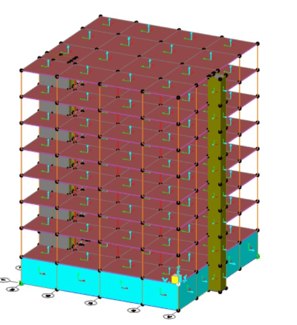
Hello, i am currently working in sap2000 and i am designing a composite steel concrete building, with steel frames and concrete floor. The issue i have is that i have very big stress on the slabs around the columns (-100knm), using the IPE 270 steel frames. But if i change them to concrete frames, the stress looks normal. What am i doing wrong, or what should i do to reduce those stresses. I shall also add that i used the transformation method for the beams, and i used property modifiers for the frame’s cross section area and moment of inertia.
 
 https://files.engineering.com/getfile.aspx?folder=f579334f-0f10-4bc7-8e3f-efd37559c0df&file=73C1247F-9D17-4EDE-9502-83A9193EF57B.jpeg
Replies continue below

Recommended for you

You will get large negative bending moments if the beams are continuous. Most composite structures use simple span beams.

If you are using continuity, the properties of the composite beams are not the same in the positive and negative bending areas.
 
But the problem is with the bending moment on the slab, not with the one on the beam. I need to know if i need to add some kind of stiffness or something to the beam to reduces the slab’s moment. I also don’t think i need a bigger steel section
 

Mr RADU,
Your internet country code , the use of steel profile IPE 270 , and units imply you are at Eurozone ..

The beams are generally designed to be simply supported ( as hokie66 (Structural) stated )

I will suggest you to look to the following documents ( SCI documents free ) and you may prefer to provide more info . regarding your modelling and frame structure.

- - -


I cannot give you the formula for success, but I can give you the formula for failure..It is: Try to please everybody.

 
Yes, some actual information about the structure would help us to give you some intelligible comments. Are there beams in both directions? Beam spans? Slab span and thickness?
 
So it is a 7 storey office building. The structure has 2 beam spans of 6 meters, and 2 spans of 5 meters on each of the 4 sides of the building. The beams are in both directions, the structure is symmetrical and the slab thickness is 14 centimetres. I also attached the sap2000 file.
 
 https://files.engineering.com/getfile.aspx?folder=0e4dd910-9090-4f51-8f1d-7c64a541f3cb&file=cmposite.sdb
I don't know much about SAP2000 but it looks like you've modeled your diaphragms (slab) with individual plates/shells in each bay. Does SAP not have a "diaphragm" (rigid or semirigid) type of tool that you can use, as opposed to manually modeling the plates like you have? Your large moments in the slab are likely due to the fact that your plates are only supported at each of the 4 corners, whereas a true semirigid diaphragm would be submeshed to much smaller elements which will add nodes along your beams. I.e., as you currently have it, your plates are only supported at the columns and not by the beams, unless the program is automatically submeshing your plates during analysis?

Snipaste_2023-04-21_08-21-27_b6pkbw.png
 
The program is meshing the plates during analysis and a diaphragm constraint was assigned to every node.
 
As i said, if i were to put concrete beams or a lot larger steel section instead of my steel frames, the moments in the slab look normal. So my guess is that this problem has something to do with the stiffnes of the frames or i need to do something for the program to figure that this is a composite structure.
 
Radu Mehelean said:
I shall also add that i used the transformation method for the beams, and i used property modifiers for the frame’s cross section area and moment of inertia.

Why did you do this? Transformation method for the beams? If I had to guess, you changed the beam properties so that they have pretty much no stiffness.

Have you looked at the SAP documentation on how to model a composite floor? It should be pretty straight forward. In other programs you would typically just assign deck properties to your floor... I've never "modeled" actual concrete shells when designing a composite floor. Normally you wouldn't even look at the moments in the slab as you are doing. For example, RAM structural system and RISA simply ignore the behavior of the actual deck (for gravity design / composite beam design) when designing the beams and simply find the loads applied and do code checks based on the assigned deck properties and beam properties.
 
I transformed the composite beam section to a steel section. And i just multiplied the cross section area with 2.1, and the moment of inertia with 2.91, nothing more.
 
I also tried not assigning the property modifiers and i got the same results.
 
At the risk of bogging a computer down drastically, what happens if you tighten up your automesh size so that you can see how sensitive the output is to mesh size. If the high stress concentrations get reduced drastically in terms of area when you do so, then it may be a modelling quirk that you need to just accept and address via engineering judgment. If the high stress concentrations remain, then I don't see another way around it.

That being said, I did find it odd that you're getting an increase in negative bending over the supports by reducing the stiffness of the system. I would've anticipating super strong steel beams resulting in high negative bending in the slab, but low stiffness steel beams would generally reduce negative slab moments due to the allowable deflection.

I guess if you are seeing really high point moments over the columns, with less stiff steel beams, that would make sense, but it would also be a bit of a modelling anomaly to me rather than a real issue.
 
Status
Not open for further replies.

Part and Inventory Search

Sponsor