Eng-Tips is the largest engineering community on the Internet

Intelligent Work Forums for Engineering Professionals

Composite tolerance question

Status
Not open for further replies.

KMHC

Mechanical
Jan 22, 2024
2
0
0
US
Hello All,
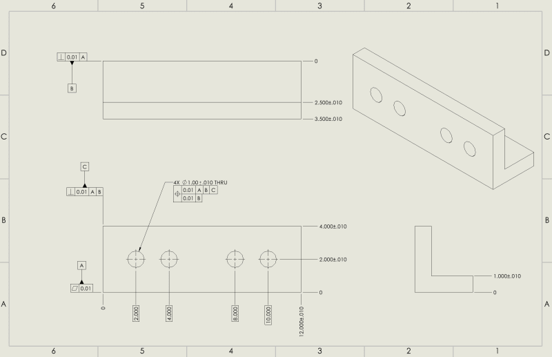
I have a question regarding composite tolerances. All the resources online that I've seen use a simple block shape for their example part with datum A perpendicular to the axis of the holes, does the bottom frame need to reference datum A or can it reference another datum like in the drawing below?
Screenshot_2024-01-22_145101_rrzdld.png
 
Replies continue below

Recommended for you

It depends on what you're trying to do. What you currently show is not correct (per ASME Y14.5) because you can't have composite (a single position symbol) with a different datum on the bottom than what's on the top. So you could either: 1) change the bottom portion to reference only datum A, or 2) split the first compartment into two segments so that there are 2 position symbols rather than one. By doing that, though, it wouldn't be called composite.
BTW, you should also include a diameter symbol in front of the tolerance numbers (for both upper and lower).

John-Paul Belanger
Certified Sr. GD&T Professional
Geometric Learning Systems
 
It might also be useful to use basic dimensions to locate the holes in the vertical direction, unless this is supposed to only be a control perpendicular to [C]

Also a little odd to have the orientation to small face of the flange rather that controlling the large face.
 
Belanger said:
It depends on what you're trying to do. What you currently show is not correct (per ASME Y14.5) because you can't have composite (a single position symbol) with a different datum on the bottom than what's on the top. So you could either: 1) change the bottom portion to reference only datum A, or 2) split the first compartment into two segments so that there are 2 position symbols rather than one. By doing that, though, it wouldn't be called composite.
BTW, you should also include a diameter symbol in front of the tolerance numbers (for both upper and lower).
Thanks for the reply.
I'd like to use a composite frame to have a tighter tolerance of the holes relative to each other vs to the rest of the part. In the training I've done, you generally see the FRTZF use the A datum only(when the orientation of the pattern doesn't matter), or the AB datums when orientation of the pattern does matter. In all of the examples though, the A datum is on the back side of the part and it perpendicular to the holes.
In this example, the orientation doesn't matter, but the A datum plane is not perpendicular to the holes, the B datum is. However, as you stated, the FRTZF needs to follow the order of the PLTZF, so I can't put just the B datum.
My question is, in this example, does using just the A datum in the FRTZF serve the same purpose as it would if the A datum was on the backside of the holes?
 
It's true that examples in the standard and in textbooks show the primary datum as the one that the holes are perpendicular to. But that's not required.
So you can have the FRTZF refer to datum A in this case. It won't serve the exact same purpose as having datum A on the backside of the holes -- it will control the holes for orientation/parallelism to datum A (rather than a perpendicularity effect), as well as the hole-to-hole location.
Also, you could omit datums altogether from the FRTZF. That would still have the holes clinging to each other.


John-Paul Belanger
Certified Sr. GD&T Professional
Geometric Learning Systems
 
Not knowing the application maybe this is not a reasonable question but here it is: Could you swap A&B in your PLTZF, then you could keep B in the FRTZF. Or even add A to you FRTZF, though this might be a little more than you really want/need.
 
Status
Not open for further replies.
Back
Top