Eng-Tips is the largest engineering community on the Internet

Intelligent Work Forums for Engineering Professionals

Position tolerance datums 3

PtoMonty

Mechanical
Sep 17, 2024
8
0
0
DE
Hello all,

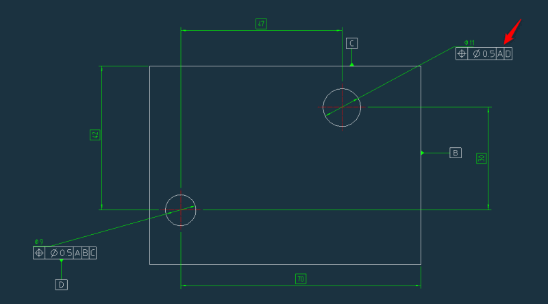
I have been trying to find an answer to this one and maybe you could give me your 2 cents. If I want to control the position of one hole in relation to another do you considered that I still need the 3 datums? Below I made a simplified drawing of what I consider to be a correct position tolerance for the hole in the top rigth. Am I till controlling all degrees of freedom? A is not in the picture but consider it as the plane defined by one of the faces perpendicular to the hole axis.

Thanks in advance.

2024-09-17_16h10_43_cdt3rt.png
 
Replies continue below

Recommended for you

3DDave,
Apologies if it's a misunderstanding on my part, but you said, "In this case all would reference [A]."
OP said, "A is not in the picture but consider it as the plane defined by one of the faces perpendicular to the hole axis."

Then I understand your suggestion as referencing only the planar datum for the position tolerances of all holes.
If that is your intention, then:
1. As I explained, the relative location between holes is indirectly controlled and results from a stack-up.
2. MMB (datum shift) is not applicable.

If It's a misunderstanding, please clarify.
 
Oh, I see. You are confused again. I never suggested using MMC. I was criticizing your blind suggestion for MMB. However if the MMC basis is used on all the holes my plan works better by not having any pathological results.

 
3DDave,
You have not suggested MMC (and I didn't say you did), but you claimed this:
3DDave said:
I gave a workable alternative that fits even better with your MMB alteration to the original posting

My MMB suggestion was related to using a pattern of two holes as a locating datum reference (meant to be secondary), as suitable to the OP's description of the "actual part." My suggestion had nothing to do with using only a planar face perpendicular to the holes as the only datum feature, as you proposed.

My suggestion was also not "blind," as I clearly indicated in which type of case it should be used (the most probable case in terms of how holes generally mate with the next part): "This is the solution I would choose, with the datum B reference at MMB (assuming the two 9 mm holes mate to two pins with non-adjustable diameter, and without a particular order)."
 
You are blind to the possible pathological outcomes. You also seem to prefer a far more complex series of steps that match those in the standard example pictures; at least that is all you have argued to do.

Your suggestion was to abandon the RMB/RFS references in favor of MMB/MMC references. Making them all MMC references and using only the primary datum plane would avoid the problem potential you blindly invite. The examples are carefully contrived to avoid exposing the problem and avoid explaining why they are so made.

I presume, because you fail to expose your reasoning, that your desire to use MMB/MMC is because the standard shows a picture of that case and not the RMB/RFS case, which the original problem required and the standard currently allows.

Burunduk said:
My MMB suggestion was related to using a pattern of two holes as a locating datum reference (meant to be secondary), as suitable to the OP's description of the "actual part." My suggestion had nothing to do with using only a planar face perpendicular to the holes as the only datum feature, as you proposed.

My suggestion was also not "blind," as I clearly indicated in which type of case it should be used (the most probable case in terms of how holes generally mate with the next part): "This is the solution I would choose, with the datum B reference at MMB (assuming the two 9 mm holes mate to two pins with non-adjustable diameter, and without a particular order)."

Yes, that was trivially obvious. It's also, not trivially, a way to get parts the customer won't want. You should understand why.
 
My suggestion to use the locating holes as datum references at MMB was not based on "the standard shows a picture of that case," but because, as I clearly stated in my earlier explanation, "The datum selection should reflect the function and mimic the assembly condition."

That means that if the two locating 9 mm diameter holes mate with two pins with some minimal clearance, allowing a given minimal amount of play/adjustment between the part and the mating assembly, this function can be accommodated and utilized as datum shift to provide additional leeway for manufacturing.
 
"The datum selection should reflect the function and mimic the assembly condition."

You don't know that function and have only a vague description of the assembly condition. You don't know the fabrication process. There are lots of ways to accept greater variation, but if you don't know the usable limits then adding additional manufacturing and inspection steps to match a picture is unsupportable.

Somewhere I have an Excel software paper gage to validated position tolerances that share a simultaneous condition. Pretty easy to use - hence the word "simpler." You probably made one for yourself. Things become far more complicated if there is a pattern of holes as a datum feature reference in a feature control frame for a position tolerance geometric characteristic.
 
Hello all again,

First thanks a lot for the discussion and ideas! I think by trying to simplify the part and its function (also can't share full design obviouslly) maybe left too much open. The assembly condition is more of less like Burunduk refers. The two 9 mm holes have pins presse in and the bushing is actually on the mating part (I then have an assembly drawing which also controlas the position of the pressd pins). The other hole (11 mm), which in the actual part is more than one, have connectors attached that mate with connectors on the counter part. That's that reason why it's important that the 11 mmm holes are dependent on the 9 mm ones. First there is a pre-alignment, achieved by the 9 mm holes (with the pressed pins) and then the connectors attached to the 11 mm holes meet with connectors on the counter part.

Going back to what jassco and Burunduk proposed I think it's what makes sense here. I had somehow achieved that in my original spec but a bit different (close to 1st option from jassco, each 9 mm hole as one datum). I like more pattern since it show better the assebmly condition which for me should be the driving force behind the spec.

Below (again very simplified compared to the actual part) is what I think represent the proposal. (I'm not using MMC since there are pressed pins in those holes).

Again thanks a lot, 1st time posting but have been reading a lot of discussions here :)

2024-09-19_10h33_10_nwjfpc.png
 
Ah, outer shape is also important to control but I also agree with jassco that profiles can be used there in realtion to the hole features.

Thanks again!
 
PtoMonty,
An important question we forgot to ask you is: what standard do you work to?
The suggestions and discussion so far were based on the implicit assumption that the drawing would follow ASME Y14.5, but if you work to ISO, there should be some modifications to the symbology to convey the same meaning, as patterns in ISO are specified differently.

Also, since the 2 locating holes are for press-fit pins, you are correct that MMB is not appropriate, but it may also be a bit more complicated to use it as a pattern.
How accurate will the "pre-alignment," as you say, by the press-fit pins be?
Often, for accurate location without over-constraining, one pin fits into a hole, and that mating sets the location, while the other pin mates to a slot that provides clocking (locks rotation). If that is the case, then the hole for the locating pin should be the secondary datum reference, and the one for the pin that mates with the slot should be the tertiary datum reference for positioning the 11 mm holes for connectors and the periphery surfaces.
 
I recall typing "It is far more likely that there is a fundamental problem with the design"

The problem now is there is a force fit that requires parts to bend in order to line up. I would not say that is more complicated. It just requires the use of a hammer. There is a complication in that the tolerance zones for are projected.

To know more requires knowing what all the materials are, how much clearance there is, and how the connectors can float to avoid becoming a part locating feature themselves.

Still, all features shown appear to engage simultaneously when fully assembled. Increasing the allowable variation will increase the allowable mis-match and may interfere with the connectors aligning.
 
Hey!

Using ISO yes. I have to check then what is the difference there.

Replying to both there are floating features that prevent an over-constrained situation.
 
PtoMonty,
Since there are floating components in the assembly, would it be correct to say that one press-fit pin will locate and the other one will clock similarly to the hole-then-slot mating method I described, or is there no such division of roles?
 
Burunduk,

Rigth now there is no such division of roles. This I have thought about in the past but we are working with existing parts which are not possible to change now (we would lose compatability with older versions). Also I think we have enough margin (the bushing is slightly larger then the pin to account for deviations) that both have the aligning function (and fight each other a bit for sure).
 
Hi, PtoMonty:

You can't press 2 pins into two holes (dia. 9mm) with the position tolerances of dia. 0.5mm wrt to datum feature A unless the plate is made from soft materials, like lumber.

Best Regards,

Alex
 
3DDave said:
The problem now is there is a force fit that requires parts to bend in order to line up.

Obviously, that was a false assumption and was just dismissed by the OP. Why assume someone would do such amateur work in the first place?
 
The main difference is the need to use the CZ modifier to force a simultaneous relationship between features rather than the default that ASME 14.5 has.

I think the original question has been answered - no, you do not always need three datum feature references (or whatever term the ISO group came up with) to locate features. Multiple features in a group can be used as a single reference to control orientation and location of the other holes.

I think ISO uses "B-B" to indicate that multiple holes are used as a single feature, for example.

Check your copy of the standard to be sure.
 
Burunduk said:
Obviously, that was a false assumption and was just dismissed by the OP. Why assume someone would do such amateur work in the first place?

Same "false" assumption as jassco made. Go nitpick him for a while. And fewer false assumptions than you have made.

So far I have no information that this new part has enough controls, such as for projected tolerance, that it will fit. The OP has not produced enough information to know that it will.
 
Hello both,

Yes the original question has been asnwered :) Only way to produce enough information is to produce all information which I can't since it's sensitive business information. I ahve simplified it to get an answer to my "basic" question. What prompted me to ask the question is that I thought my spec was controlling all degrees of freedom but my supplier came back with position measurement that only took into account perpendicularity to A and one single axis (horizontal let's say). So as far as I saw their interpretation was incorrect. With the info you all have provided I will try to strenght the spec (and maybe simplify it).

In ISO like you said I should probably have two datums and refence them as A-A, or B-B (which I was already doing in the first place).

3DDave, Please disregard the dimensions and tolerance values. They were picked random just to have numbers there. I don't fully understand what you mean with you can press them. They are individual pins. You press one, then the other. THen the part (with two pins), mates with the counterpart that has two bushings. Anyway thanks also for your input!


Another important difference between the ISO and ASME standards, in the context of what you need, is that in ISO in order to apply a simultaneous requirement between two or more geometric tolerances of position or profile, it’s not enough for them to reference the same datums in the same order and with the same material boundary modifiers, like in ASME. In ISO simultaneous requirements must be explicitly specified. This is done by writing SIM next to each tolerance indicator.

In your case, this is relevant to the position of the holes and the all-around profile you will specify for the peripheral surfaces, to relate the 11 mm holes with the periphery of the part.
 
Back
Top