nmine
Mechanical
- Jul 7, 2023
- 15
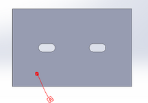
I have had this question for sometime and have only seen instances where there is a hole as datum b and plane of a slot as C. What if you have a flat plate with two slots and you want to control the outer edges of the plate using a profile tolerance with respect to the slots (slots are centered). How would you use the slots as a secondary/tertiary datum to control the outer edges of the plate to the slots?