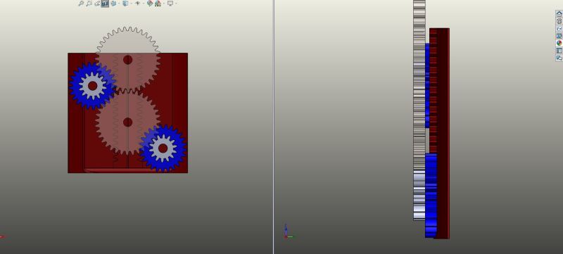
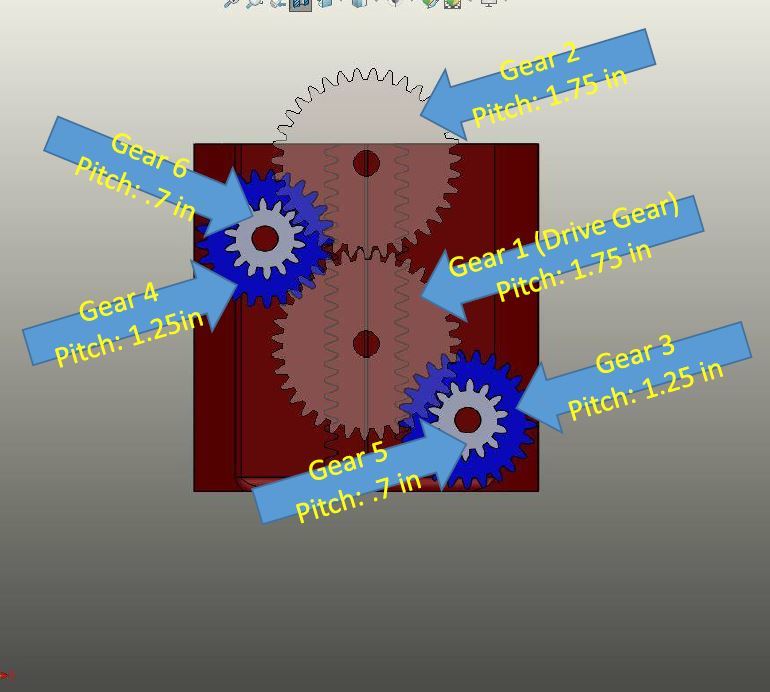
It has been a long time since I have dealt with gear trains. Probably since my college days and I am now 43 years old. Anyway, I am working on something and I would like someone with more experience with gears to offer their input. Attached is a PDF showing my compound gear train interacting with a rack. I included the pitch diameters of the spur gears, although these are just randomly picked gears sizes with a diametral pitch of 20, for this example.
Allow me to give a verbal description of the gear train. I have a drive gear (Gear 1, Transparent) which meshes with another gear of equal size (Gear 2, Transparent) and a smaller gear (Gear 5, Grey). Gear 2 meshes with a similar in size as gear Gear 5 (Gear 6, Grey). Gear 5 and Gear 6 form compound gears respectively with Gear 3 (Blue) and Gear 4 (Blue). Gear 3 and 4 mesh with the rack (Red).
My question is what is the amount of the linear force imparted to the rack?
I started my evaluation by assuming an input torque of 100 in-lbs and using the equation Wt=2*T/d. With "Wt" being transmitted force, "T" is torque and "d" is the pitch diameter. I only evaluated half of the gear train (Gear 1, Gear 3, and Gear 5) because I assumed if I had done the free body diagram I would have ended up with half of the force on Gear 3 and half of the force on Gear 4 then adding the two together to get the total force imparted to the rack. This might be an incorrect assumption, but I do not believe it is incorrect.
For Gear 1 this gives a Wt equal to 114.3 lbs. Then using half of the pitch diameter for Gear 5, I calculated a torque of 40 in-lbs imparted to the compound gear of Gear 3 and Gear 5. Again using the formula for transmitted load, Gear 3 imparts a linear force of 64 lbs to the rack.
Is my reasoning for the problem valid? Is the solution valid? If I am wrong, please advise.


