Continue to Site

Eng-Tips is the largest engineering community on the Internet

Intelligent Work Forums for Engineering Professionals

  • Congratulations KootK on being selected by the Eng-Tips community for having the most helpful posts in the forums last week. Way to Go!

Compression force in beam flange with column on top and below the beam. 1

Status
Not open for further replies.

NL4L1F3

Mechanical
Mar 9, 2018
30
Hello,

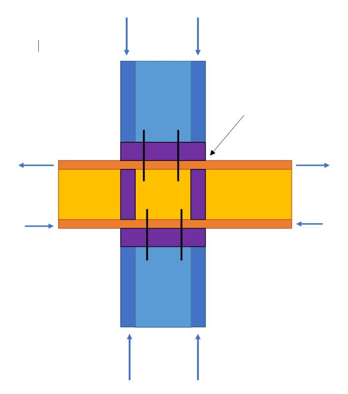
Lets say i have the situation in the image below.
Afbeelding_kolom_doorgaande_ligger_a61fmz.png


Lets say that the stress in the column is near yielding. The compression force has to go trough the plate, then the flange and then the stiffeners down to the other column.

Wouldnt this mean that the flange under the column is also close to yielding and any bending moment added to the beam would result in failure of the beam. because these stresses need to be combined? Or does this effect not have to be checked? i have searched but couldnt really find anything about this.

Thank you.
 
Replies continue below

Recommended for you

Your tension/compression from flexural moment is in a different direction than vertical axial compression. When we talk about the stress in a member, it's based on a certain direction. For example, we check shear and bending separately. Combining them means taking the stress at a 45 degrees angle, which is kind of a vector rotation / resultant magnitude type of thing, but codes generally don't make you do that so I don't see a reason to.

Since you have a bearing plate, you can check the bearing stresses. I don't know what code you use, but AISC has a section on that.
 
Yea the stress is at a different angle. But combined and the calculated with lets say von mises the total exceeds the limit of the material. So why shouldnt it be checked? Is it stated somewhere?

Im from eu but will check the aisc
 
NL41F3 said:
Lets say that the stress in the column is near yielding.

- Yeah, if the axial in the column is really that high, I feel that this is a worthwhile concern.

- Something akin to a Von-mises check might be advisable.

- For the kind of load that column yielding implies, I'd be inclined to explore alternate connection typologies.

- For compression, perhaps there is a way to use the ultimate steel stress locally rather than the yield stress? I've only availed myself of this in tension.
 
I couldn't find anything in AISC code that's really comparable to this situation. This is almost more of a mechanical engineering type of question, like in a long pressure vessel that's subject to both high internal pressure and global flexure. I'd just do a generic yield stress check on the resultant stress. The reduction/safety factor (LRFD/ASD factor) is something I'm not sure about, because it's different for flexure, shear, bearing, compression, interpolating between flexure and compression, etc, so I'd just use the one for compression. The reason I'd do a generic check is because we're not concerned about things like buckling.

I'm guessing it's a short column or well braced? Stresses in columns don't usually reach yield stress; they're governed by buckling. Maybe that's why I couldn't find anything on this...

This thread has an interesting discussion at the end about ductility that you might find useful, and it kind of expands the reasoning about why stresses are checked in separate directions:

Something else to think about: Maybe you don't use the compression at the bearing plate, but rather in the stiffener. So the black arrow you showed should be a little lower. The bearing plate is spreading out the load, but the web stiffener is concentrating it. How much of that spreads through the flange and into the web would be negligible, and the main concentration would be at the stiffener.
 
The code is just the code. It is not all encompassing. Depending on your locality you might consider it 'guidelines' or the 'bare minimum under law'.

Our jobs as Professional Engineers is to design suitable structures, often that should involve additional thought beyond what is codified.

So of course it should be checked, you shouldn't need a code to tell you that.
 
Thank you all for the replies.

Yes indeed this is a short but heavy column where buckling is still governing but the stresses are very high(in both the beam and the column). This was the detail given by the EOR and architect.but we need to make the calculations.

Software we use for detailing does not check this combined stress, as it makes plate elements of all the flanges and other plates. So i was wondering if it was something that had to be checked or not.

I will see where it goes and probably use thicker stifferners/ and the weld to the stiffeners to spread out the load over a bigger flange area.

Though i do think that if you actively check the stresses with von mises in details like lets say moment connections or other details like this the stresses will often be higher then what we actively check for with normal code checks. (And have yet to see someone checking this failure point).

 
Did you check AISC specifications section J10? It specifically talks about these configuration of transfer of forces through the wide flange section. The section above and below trying to effectively yield the wide flange in compression normal to its axis.
 
L4L1F3 said:
I will see where it goes and probably use thicker stifferners/ and the weld to the stiffeners to spread out the load over a bigger flange area.
That seems a poor solution to your problem.

Your challenge is excessive stresses in the flanges. If you want to reduce the stresses in the flanges then you'll need thicker flanges no bigger web stiffeners. Consider a bigger beam. Or flange doubler plates. (A bigger beam is generally cheaper than flange doubler plates.)
 
human909 said:
That seems a poor solution to your problem.

Your challenge is excessive stresses in the flanges. If you want to reduce the stresses in the flanges then you'll need thicker flanges no bigger web stiffeners. Consider a bigger beam. Or flange doubler plates. (A bigger beam is generally cheaper than flange doubler plates.)

The EOR calculated the required profiles and we make the calculations of the details. The stresses are a bit lower then yielding but in my example i said yielding to get my point across.

In the situation that the column flange is close to yielding the thicker beam flange would not increase the resistance much, as the loaded area is the smallest area of the flange+distribution over the end plate or the stiffener. With the thicker stiffeners and bigger end plate the load of the column flange is distributed over a bigger area in the beam flange lowering the compression stress in the flange? And thus allowing a bigger tensile force from the moments in the beam?

I agree if the beam was near yielding thicker flanges of the beam would help a lot aswell.
 
It’s unusual for a beam column joint to be detailed this way. Beam end plate moment connections to continuous columns are more typical and the failure modes and design procedures are covered thoroughly in the codes and literature.
 
Status
Not open for further replies.

Part and Inventory Search

Sponsor