HDStructural
Structural
- Apr 24, 2024
- 123
Hello all,
First time posting here.
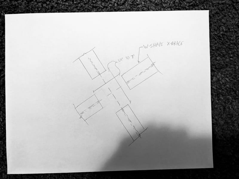
I am working on a project that has W-shape x-bracing that was designed for tension and compression. They cannot be considered tension only. Normally, we would make one of the braces continuous and the other brace would be cut in half, framing into the continuous brace. The continuous brace would be checked to make sure it is stiff enough to "brace" the two partial braces framing into it. However, the steel has already been produced and instead of having one continuous brace and one broken up brace, both braces were broken up and must connect in the middle.
I believe the best way to design this connection would be to have gusset plates on the outside of the flanges. The built up section properties (I, r, etc.) of the two gusset plates should exceed the properties of the W shape braces to ensure that there will be no global buckling of the brace. Additionally, the individual gusset plates must be checked so that they wouldn't buckle between the connection points. I think this could be done using a k of 0.65 since the connections to the W shape flanges would be rigid (probably a C shaped weld with all dimensions being greater than 10"). The gap between the braces for the connection is up to 84" at some locations, so the plates could get pretty hefty based on kl/r.
Do you think that this should also be analyzed as a built up member? That would impose much more stringent kl/r requirements on the individual gusset plates that would be difficult to meet (0.86 instead of 0.65, individual kl/r must be less than 3/4 of the gross sections kl/r, etc.).
How would you design this connection? Am I missing anything?
First time posting here.
I am working on a project that has W-shape x-bracing that was designed for tension and compression. They cannot be considered tension only. Normally, we would make one of the braces continuous and the other brace would be cut in half, framing into the continuous brace. The continuous brace would be checked to make sure it is stiff enough to "brace" the two partial braces framing into it. However, the steel has already been produced and instead of having one continuous brace and one broken up brace, both braces were broken up and must connect in the middle.
I believe the best way to design this connection would be to have gusset plates on the outside of the flanges. The built up section properties (I, r, etc.) of the two gusset plates should exceed the properties of the W shape braces to ensure that there will be no global buckling of the brace. Additionally, the individual gusset plates must be checked so that they wouldn't buckle between the connection points. I think this could be done using a k of 0.65 since the connections to the W shape flanges would be rigid (probably a C shaped weld with all dimensions being greater than 10"). The gap between the braces for the connection is up to 84" at some locations, so the plates could get pretty hefty based on kl/r.
Do you think that this should also be analyzed as a built up member? That would impose much more stringent kl/r requirements on the individual gusset plates that would be difficult to meet (0.86 instead of 0.65, individual kl/r must be less than 3/4 of the gross sections kl/r, etc.).
How would you design this connection? Am I missing anything?