Eng-Tips is the largest engineering community on the Internet

Intelligent Work Forums for Engineering Professionals

Compressor design

Status
Not open for further replies.

AnhsirkT

Chemical
Aug 24, 2020
85
0
0
IN
IMG_20200913_191837_xjjwtl.jpg

Why these two design have difference?
What is the reason for that?

Do not think twice
 
Replies continue below

Recommended for you

so overall temp will reduce but not less than suction temp (it will in b/w both of them ) so no chance of liquid droplets

You seem to be comparing at equal pressure level. The reality is that pressure at discharge is higher than suction which means dew point may increase and it may increase significantly or not depending on your liquid-vapor phase envelope. It may work but we do not have all the details.
But certainly, relying on suction temperature as criterion means you are ignoring the above.


If you plan an escape, you must succeed as if you fail, you will be punished for trying. Never say or write down your plan. Heart is the only place where secrecy is granted.
 
I think both pressure will be approx at same level
Like 1S discharge at 2.4 bar and second suction is at 2.3 bar.
So temperature of mixture will be above dew point bcz it is pure ethylene which will not condense at this condition
 
For dew point analysis @ main feed it is : pressures @ 1st stage suction and 2nd stage suction.
See attached a generic example to illustrate the concept (applies generally).
EthylenecompressorDP_x7eygu.jpg

Obviously considerations are to be taken into account, for example if side stream and main feed stream have identical gas composition.
If you have superheated pure Ethylene, then what is the knock out drum purpose?
 
Actually KO drum just for safety if any liquid appear then drain out (dry drum).
Ethylene in theses drums at superheated condition (10C more than dew point)
So final combination also at superheated condition there is never any condition at which ethylene get condesed.
Let's say 2S stage suction at dew point (7 bar -62C) than 1 S dicharge will definitely superheated after compression (7.2bar 20or 25C) and mixture will be will give temperature more than -61C so superheated
 
except suction at dew point and 2S high flow than 1S discharge

Reference to your quote for the part in bold:

If you have pure Ethylene (main feed and side stream being identical gases) and side stream is super heated, not even then.
 
If side stream not superheated than also some things mixing with this is superheated (same ethylene )than mixture will be superheated
'' Let's say 2S stage suction at dew point (7 bar -62C) than 1 S dicharge will definitely superheated after compression (7.2bar 20or 25C) and mixture will be will give temperature more than -61C so superheated''
 
Thank you Mr rotw
I will consider this facter for design 2 .
Any other things which I am missing or any disadvantages of Design 2?
 
By the way, can you give the pressures, expected temperatures and flow capacity from first suction to final discharge?

If you plan an escape, you must succeed as if you fail, you will be punished for trying. Never say or write down your plan. Heart is the only place where secrecy is granted.
 
You did not provide the capacities? Despite this missing information, here are some thoughts:

Are looking at the most effective design? see explanation below (referring to multistage centrifugal compressor design; CAUTION: the below preliminary analysis is depending on the flow capacities involved which you did not provide):

1 S 1.4BAR D 8.2BAR -> compression ratio requires 4 impellers @ max peripheral speed < 290 m/s
2 S 8 BAR 10.5BAR -> compression ratio requires 1 impeller @ max peripheral speed < 200 m/s
3 S 10.3 BAR 17BAR -> compression ratio requires 1 impeller @ max peripheral speed < 290 m/s

Mobilizing a dedicated compressor casing for a single impeller does not look very economical with reference to stage 2 and 3.
The selection should fit a single horizontally-split casing of six impellers 4+1+1 (3 sections) and with two injections (side streams).
This way you do not have to worry about design 1 vs. 2, basically the mixing occurs inside the compressor (stage diffuser / return channel).

The flow capacities involved, will dictate if the flows are realistic for centrifugal type design and whether you need 3D type of impellers which would add some stringency to the rotor-dynamics, should it be all 2D's type this does not appear as a difficult machine to build.

If you plan an escape, you must succeed as if you fail, you will be punished for trying. Never say or write down your plan. Heart is the only place where secrecy is granted.
 
Yes I am planning to make 2 casing
First with 1 section
Second casing with two sections(2&3)
Flow is 200tonnes/hr.
But design 2 required only 4MOV moter ooerted valve to isolate casing and no chance of condensate so is it good?
Your singal casing idea is good.
but if two casing provide then first casing discharge should go to second casing via KO drum or directly in line ?
 
200 t/h is the inlet rated capacity? it is also needed to know side streams to have the complete pictures.

Anyway, this would require a single casing, 6 stage horizontally-split compressor (roughly: 4 x 900 mm + 1 x 650 mm + 1 x 900 mm), with two injections. The 1st two impellers of the 1st section should be 3D type and for 2nd section a 2D type impeller should be possible. Rated speed ~ 5500 rpm.

I would be preferable to balance the load / inter-stage pressure between 1st and 2nd stage so to have 3 stage on 1st section, if process allows for this adjustment.


Edit: a more than one casing - solution could cost between 1 to 1.5 Million USD extra in terms of capital equipment cost. Other potential impacts:
-Increased installed costs;
-Additional process and utility piping and instruments;
-Substantially increased footprint and equipment weight;
-Increased utility consumption;
-Additional dry gas seal panels, bigger lube oil system size.

What driver type are you considering.
 
It is needed the capacity through each stage the machine not just the total at outlet; so you have

1st stage = 80 kg/h through stage
2nd stage = 80 + 80 (injection) = 160 kg/h through stage
3rd stage = 160 + 40 (injection) = 200 kg/h through stage

is this correct?

If you plan an escape, you must succeed as if you fail, you will be punished for trying. Never say or write down your plan. Heart is the only place where secrecy is granted.
 
right it is t/h.

Ok, something like this:

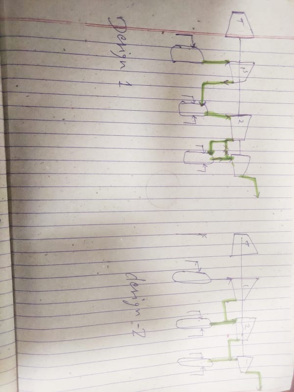
4 x 900 mm + 1 x 630 mm + 1 x 900 mm

Absorbed power ~ 6.8 MW (total)
Rated speed ~ 5500 rpm.

1st impeller 3D high Mach followed by conventional 3D or a 2D. The rest are all 2D impellers.
At first sight, does not seem to be any problematic rotor-dynamically.
I do not see any reason for a two casing solution let alone a three casing.

On the injection lines, you may need to put a knock out drum on each line, but not even sure of this, ask process engineering. Ask them also if there is room to adjust the load between 1st and 2nd stage (inter-stage pressure) - but it is not a must.

If you plan an escape, you must succeed as if you fail, you will be punished for trying. Never say or write down your plan. Heart is the only place where secrecy is granted.
 
You're welcome.

If you plan an escape, you must succeed as if you fail, you will be punished for trying. Never say or write down your plan. Heart is the only place where secrecy is granted.
 
Please clarify also
1.How many impeller we can put in one casing?
2.maximum tip velocity of impeller should be 200-275m/s right?
3.how much you assume the maximum head produced by one impeller ?
 
Status
Not open for further replies.
Back
Top