Hi,
New FE user here. I ran a few test simulations for a nozzle pipe junction to be evaluated using shell elements. For the analysis, the internal pressure, constraints, mesh size, etc. have been kept identical. Thickness = 7 gauge carbon steel. I am particularly interested in the nodal forces of element on the toe of the weld on the longitudinal plane.
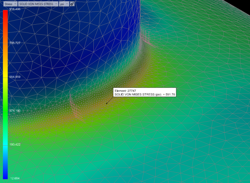
3D tet mesh:

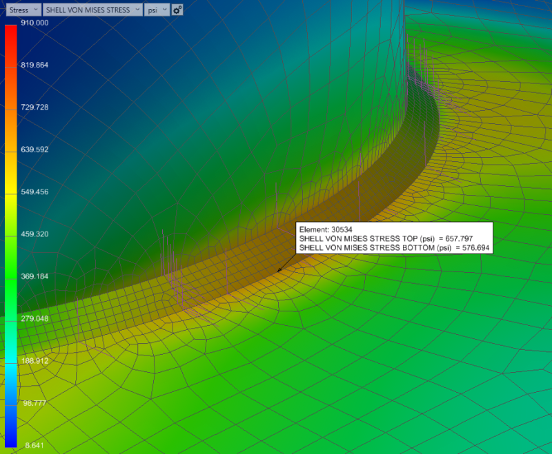
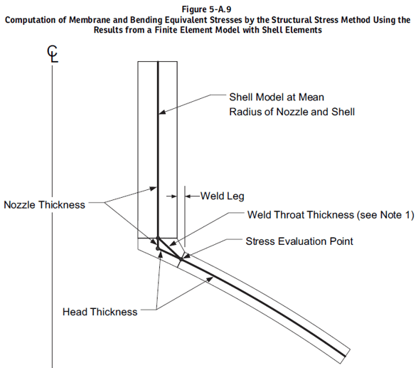
2D mesh based on ASME VIII div. 2 Figure 5-A.9, weld throat length = 0.15" (oversized)

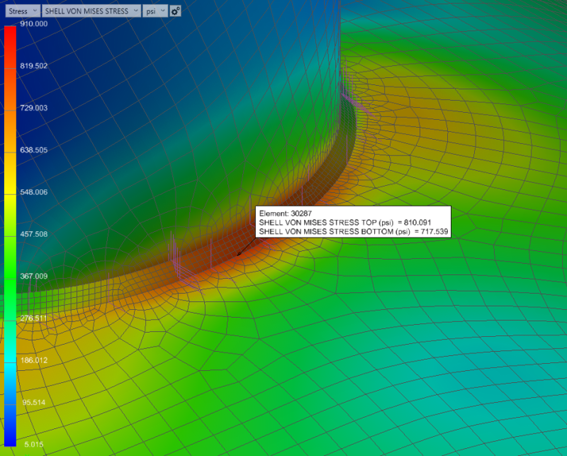
2D mesh based on ASME VIII div. 2 Figure 5-A.9, weld throat length = 0.135" (correct size)

What is the correct approach to size the weld throat length for the analysis? I'm a bit lost as I'm unable to validate the 2d and 3d analysis. I would believe that the top surface Von Mises stress at the node under consideration would be in the 600-650 psi range, but the method i've followed based on the guidelines in the code yields values that are about 100 psi higher.
Thank you
Reference:

New FE user here. I ran a few test simulations for a nozzle pipe junction to be evaluated using shell elements. For the analysis, the internal pressure, constraints, mesh size, etc. have been kept identical. Thickness = 7 gauge carbon steel. I am particularly interested in the nodal forces of element on the toe of the weld on the longitudinal plane.
3D tet mesh:

2D mesh based on ASME VIII div. 2 Figure 5-A.9, weld throat length = 0.15" (oversized)

2D mesh based on ASME VIII div. 2 Figure 5-A.9, weld throat length = 0.135" (correct size)

What is the correct approach to size the weld throat length for the analysis? I'm a bit lost as I'm unable to validate the 2d and 3d analysis. I would believe that the top surface Von Mises stress at the node under consideration would be in the 600-650 psi range, but the method i've followed based on the guidelines in the code yields values that are about 100 psi higher.
Thank you
Reference:

