Continue to Site

Eng-Tips is the largest engineering community on the Internet

Intelligent Work Forums for Engineering Professionals

  • Congratulations KootK on being selected by the Eng-Tips community for having the most helpful posts in the forums last week. Way to Go!

Concentric Tubes in Bendine 2

Status
Not open for further replies.

toothless48

Mechanical
Oct 27, 2014
29
Hello all, I am analyzing a design that involves a stainless steel tube in bending. This tube is reinforced with a smaller "doubler tube" snugly fit inside (its OD being equal to the larger tube's ID). The tubes are not bonded, and are free to slide, ignoring friction. I have scoured the internet and my textbooks to no avail - how is the section modulus for this configuration calculated? The area moment of inertia of the cross section is the same regardless of the tubes being bonded or free to slide. I assumed, similar to composite beams, that two sliding tubes would be less stiff than one thick tube... Is this not true?

Many thanks
Mike
 
Replies continue below

Recommended for you

the two tubes would deflect the same, I agree; but would the deflection be the same as one thick tube ... I don't think so.

surely in the thick tube there is some stress where the parting plane is in the two tubes ? surely this affects the results.

surely two tubes with an interference fit would behave differently compared to two tubes with a sliding fit ?

two tubes with an interference fit would behave like a single thick tube.

another day in paradise, or is paradise one day closer ?
 
rb1975 said:
do you see a different if the inner tube is interference fit ?

In theory no. Again, because the strain diagrams are identical, there's no need to engage friction whether it's available or not.

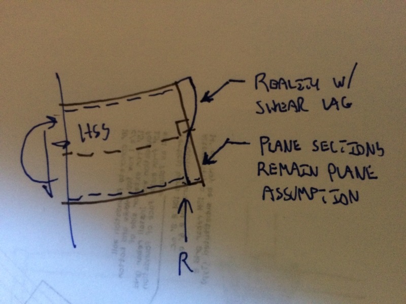
In reality, I would expect a tight friction fit to change stresses a bit. Intentionally, I've just been discussing flexural behavior assuming that plane section remain plane. In the wild, the strains at the extreme ends of the two tubes would probably differ a bit due to shear lag up the sides of the tubes. That difference would be, at least partially, ironed out by the action of the friction generated at the interface.

rb1957 said:
in the single thick tube, is there no stress on the parting plane ? (I don't think so, but there is in the two tube case)

I would expect there to be some stress at the faux-interface plane in the solid section case. This is conceptually similar to what I mentioned above with respect tot he interference fit. Continuity in the material would tend to enforce strain compatibility more convincingly than shear lag.

rb1957 said:
in the two tubes, a single point load on the outer tube would not load the inner tube as a point load (IMHO) but the inner tube would be loaded (and the outer tube relieved) by a distributed load (as the outer tube bears against the inner one).

No doubt, this phenomenon would have an effect on local bearing stresses etc. As JAE described, however, it wouldn't impact theoretical flexural strains.

SAIL3 said:
this is a slip fit to begin with....if the assumption is that there is no effective means of transferring horiz shear between the 2 tubes, it then poses the question why ,in this application, is it necessary at all....one could apply this reasoning to a laminated wood beam and assume that the bonding between layers as being unnecessary...

That's precisely the point, it's not necessary in certain cases. Regarding the wood example, consider:

CASE 1: tube and tube as described here.

CASE 2: 4X10 main with with a pair of 2x6 sides for reinforcing. The center lines of all member align.

For both cases, I would submit that the following is true:

1) Both members need some mechanism by which vertical load can be transferred from the directly loaded member to the member not directly loaded. Without this, the curvatures of the various members cannot be made to match.

2) For the tubes, the vertical load transfer mechanism is some complex bearing situation, as intimated by rb1957.

3) For the wood, it's vertical shear transfer in the bolts.

So the bolts in the wood are necessary, just not for horizontal shear transfer. Their role is solely to transfer vertical shear and enforce curvature compatibility among the plies. Fundamentally, this is why we don't have to bother with VQ/It forces when we laminate multi ply wood beams of the same depths. There's just no demand for horizontal shear transfer.

I like to debate structural engineering theory -- a lot. If I challenge you on something, know that I'm doing so because I respect your opinion enough to either change it or adopt it.
 
KootK said:
I_composite = I_non-composite. Do you dispute that? If not, why would you think the composite section to be any stiffer?

rb1957 said:
"Do you dispute that?" no, the math is straight forward; but will be beam behave that way is a different question.

rb1957: you confirmed that you agree that I_comp = I_non-comp. With that being the case, how do you justify deflection being different for the two cases? EI is the same for both. How is it that you see the beam behaving differently from our normal Bernoulli assumptions? Is it more than an intuitive feel?

I like to debate structural engineering theory -- a lot. If I challenge you on something, know that I'm doing so because I respect your opinion enough to either change it or adopt it.
 
Koot..the wood beam example should be horiz plies......you are also assuming plane sections remain plane in the 2-tube-example..I can not see any mechanism to accomplish this if there is no horiz shear capacity between the 2 tubes.....
 
SAIL3 said:
Koot..the wood beam example should be horiz plies..

It can't be because the horizontal shear transfer would be required. With horizontal plies, the important feature of this thread's example is lost: the neutral axes of the plies, acting independently, are no longer aligned vertically.

OP said:
you are also assuming plane sections remain plane in the 2-tube-example..I can not see any mechanism to accomplish this if there is no horiz shear capacity between the 2 tubes.....

The mechanism is web shear (and potentially lag as I mentioned above). Same as how strain compatibility is enforced between the flanges of a stand alone I-beam. With tube in tube, the two tubes do this job independently but the net effect is the same.

I like to debate structural engineering theory -- a lot. If I challenge you on something, know that I'm doing so because I respect your opinion enough to either change it or adopt it.
 
Quote (KootK)
I_composite = I_non-composite. Do you dispute that? If not, why would you think the composite section to be any stiffer?

Quote (rb1957)
"Do you dispute that?" no, the math is straight forward; but will be beam behave that way is a different question.


I was using "lawyer speak" ... I agree with the math presented, I just don't think the underlying proposition (that deflection of a single thick tube = deflection of two tubes) is correct.

We agree that there is some stress happening on the "faux parting plane" in the single thick tube. I think two tubes with interference fit would exhibit the same behaviour as I think there's something there that'll allow the stress to develop (the interference between the two tubes allows them to talk to one another). If there's a sliding fit then this stress can't develop and so the two tubes are different to the single tube.

How big a difference ? As I've proposed, if the outer tube has a point load, the inner tube will have a distributed load, maybe something like a sine wave. If the outer tube is loaded by a distributed load then I think the difference is very small.

another day in paradise, or is paradise one day closer ?
 
if you say so, Koot.....but, I detect Timoshenko stirring in his grave.....
 
There are several unusual things about tackling this problem, and the best way, of course, isn’t to obscure the real facts of the matter, how the structure really acts. By the nature of makeup of the total shape, there is an unusual math/geometry/section property anomaly in this problem. Since the center is the same for the two pipes, they have individual moments of inertia (MoI), as structSU10 shows above, and adding these two MoI’s gives the same value as a single shape (combined, composite? shape) having the inner min. pipe i.d. and the outer max. pipe o.d. You would never get those two pipes together without some fair sized dia. gap, particularly at 6' long. Thus, there can be considerable slippage btwn. them in action, and some friction action too. You might press two pipes, only 6"-8" long together, and actually have a press fit condition, more like a composite section, but pretty complex to define at the interface.

I maintain that the two pipes do deflect together (in unison), but they share the load in proportion to their relative stiffness’, functions of their MoI’s, E’s and lengths. Since E and L are the same for each, the MoI is the controlling factor. The outer pipe will carry more of the load because of its greater MoI. The section modulus (Sx) must be figured for each pipe, and because of the slip btwn. them there is no single element equivalent for this part of the problem. On the 6 - 12 o’clock axis the stresses might look something like this (no real numbers were run as structSU10 did): near 6 o’clock, at outer o.d. (3"/2) σ = +50ksi; at outer i.d. (2.75"/2) σ = +45ksi; at the inner o.d. (2.68"/2) σ = + approx. 50ksi; at the inner i.d. (2.5"/2) σ = + approx. 45ksi; at the N.A. σ = 0ksi; near 12 o’clock, at the inner i.d. (2.5"/2) σ = approx. -45ksi. Note that at the (2.75"/2) or at (2.5"/2) levels, or any other level the stresses are not the same in the inner and outer pipes, but the deflected shape is.
 
that's another way to look at the problem ...
the stresses in the smaller tube must be higher than the larger one as their deflected shape is the same and the smaller tube has a smaller I/y (proportional to OD^2*t)

another day in paradise, or is paradise one day closer ?
 
SAIL3 said:
but, I detect Timoshenko stirring in his grave

Rolling on his side to make room for some clapping? Just foolin'... I know what you meant.

As I see it, the sharing of a common strain diagram is what puts the "composite" in composite behaviour. A cross section could be comprised of interplanetary dust particles seperated by miles for all the difference it makes in Bernoulli flexure. So long as all of the parts follow the same strain diagram, an equivalent section is possible for stress and deflection calcs. And simple as well. All equivalency requires is the ignoring of boundaries / empty space in recognition of strain matching there.

I like to debate structural engineering theory -- a lot. If I challenge you on something, know that I'm doing so because I respect your opinion enough to either change it or adopt it.
 
rb1957 said:
the stresses in the smaller tube must be higher than the larger one as their deflected shape is the same and the smaller tube has a smaller I/y (proportional to OD^2*t)

I believe that stresses will be higher in the larger member. Consider:

1) again, that common strain diagram and;

2) the the outer tube attracts more moment which will increase stress.

I like to debate structural engineering theory -- a lot. If I challenge you on something, know that I'm doing so because I respect your opinion enough to either change it or adopt it.
 
Kootk is definitely theoretically correct, there is zero shear demand along the length of the interface of the two pipes, neutral axes coincide so no shear flow between them, and it is also obvious in this case by intuition that the members behave as if they were one solid member for the case of bending. But if there is a non negligible gap between them, some kind of wonky load sharing occurs, where at the mid point the top of outer pipe bears on the inner pipe, and the supported ends the bottom of the inner pipe bears on the upper pipe (assume single span simply supported with a point load at mid span). Based on OPs description though that doesn't apply to his problem.
 
RB:
I haven’t put any real numbers to the real problem yet. I am suggesting (I believe) that the two pipes will be at about yield (50ksi, whatever) at their own extreme fibers at about the same time. This is due to their own/individual M/Sx, and due to their different loading proportion, sharing, which is due to their different stiffness’. I agree with you that there will be some funny localized loadings or stresses; your example, the point load on the outer pipe, being somewhat distributed to the inner pipe at the same general location, some length on the beam. For the slip fit, the two pipes are more or less forced to deflect the same, +/- a few hundredths or thousandths of an inch, by their almost intimate contact. But, these are smaller than the straightness or ovalty tolerance in the pipe, thus some interference in a long length. I also agree with Koot that the interference fit will introduce some new triaxial, very complex, stresses into the picture, that none of us really want to try to define here. The point that I was trying to make is that the two pipes act independently from the normal bending stress standpoint and that except at the N.A. level, where σ = 0ksi in both pipes, the stresses are not the same at any other level in the beam system. Certainly not like someone might be inclined to think if they went too far down the single composite section ‘pipe line,’ er path. I’ll leave the more complex secondary affects to another day.
 
if you have two tubes, a large one and a small one, and deflect them the same; the moment in each is proportional to I (thinking d(x) = M/EI*...) and so the smaller tube has a lower bending stress (because the extreme fiber is less) ... yes, not what I posted before (sigh).

If both tubes are bending along the same deflection curve then stress is proportional to distance from the NA (as M/I is constant) ... not what I posted before ... I still think that losing what is happening on the "faux parting line" should have an effect.

another day in paradise, or is paradise one day closer ?
 
KootK:[tt]
KootK said:
In reality, I would expect a tight friction fit to change stresses a bit. Intentionally, I've just been discussing flexural behavior assuming that plane section remain plane. In the wild, the strains at the extreme ends of the two tubes would probably differ a bit due to shear lag up the sides of the tubes. That difference would be, at least partially, ironed out by the action of the friction generated at the interface.
What do you mean by "assuming that plane section remains plane". Are you referring to the cross section relative to the NA? Why would it be out-of-plane? Also, where does shear lag come into play? At the released ends of the tubes?

This is now beyond the scope of my analysis, but it is good to know/understand nonetheless.[/tt]
 
Yeah, it's beyond the scope of all of us that spend our time out in profit-land trying to earn a living. See if the sketch below helpes at all. It applies at all points along the length of a member with the effect being most pronounced at the locations where shear is at its peak values. The effect is usually so minor as to be of no practical consequence.

IMG_5340_geo7nw.jpg


I like to debate structural engineering theory -- a lot. If I challenge you on something, know that I'm doing so because I respect your opinion enough to either change it or adopt it.
 
It seems like they should both be able to develop their individual full plastic moments.

The larger tube just gets there first.
 
Long thread and maybe this has already been discussed, but how exactly do you fit one tube inside the other for the full length? Has this been done before? Seems to me typical construction tolerances would make this extremely difficult to install.

Interesting academic discussion though.
 
i think the first question is why would you (insert a tube in a tube with a sliding fit) ? maybe to reinforce and existing tube ??

practically, since we are talking about a close tolerance fit, i'd probably freeze the inner tube, having verified that it won't be loose in it's final position. maybe scan the ID of the large tube to get a true representation. and, yes, I realise that these ideas are not normally practical.

another day in paradise, or is paradise one day closer ?
 
jdgengineer said:
how exactly do you fit one tube inside the other for the full length?
Just spit on it a few times and ram it home?
 
Status
Not open for further replies.

Part and Inventory Search

Sponsor