Eng-Tips is the largest engineering community on the Internet

Intelligent Work Forums for Engineering Professionals

Conceptual Design Review 1

Status
Not open for further replies.

tmalik3156

Structural
Jun 21, 2021
92
0
6
CA
Good day all.

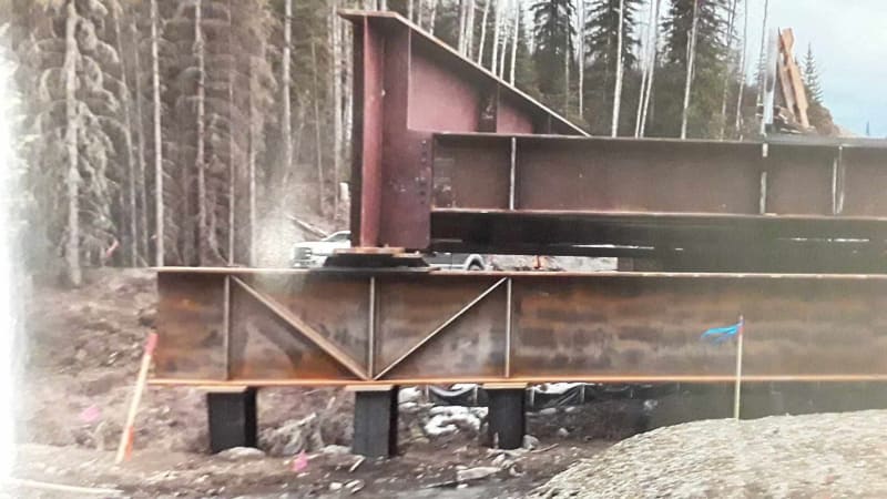
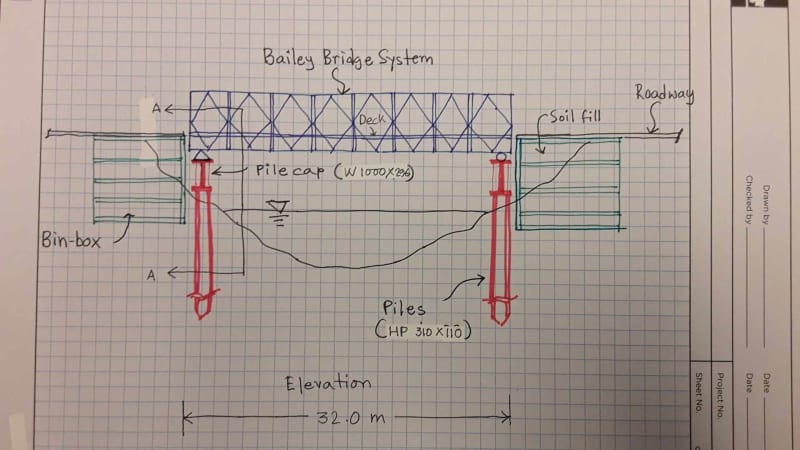
A 32 m long bridge is to be constructed on a rural road over a small river. Sketches of the conceptual design are shown below.
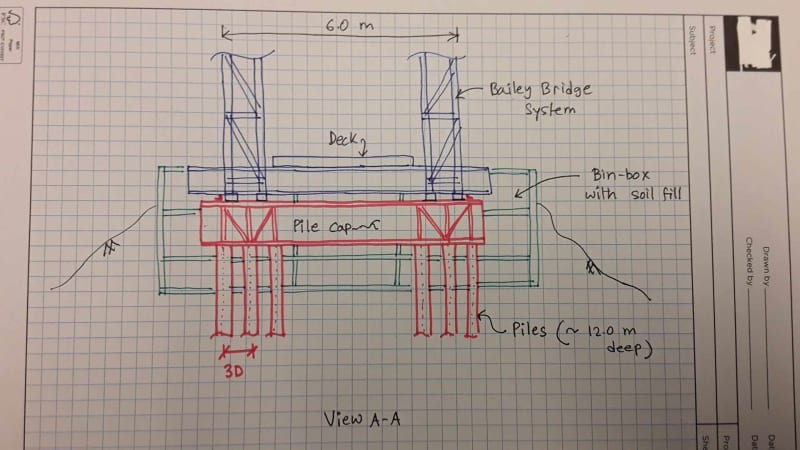
Kindly take a look and advise if this concept looks acceptable. For example, what do you think of using a single row of piles, having no batter, use of a bin-box to retain the soil behind the pile cap?

It's a low budget project, and construction simplicity is preferred.
Do you see any obvious mistakes in this concept design?

ULS vertical load at each corner of the superstructure = 800 kN. ULS longitudinal load at each fixed bearing (due to Breaking force) = 180 kN - generating a deflection at pile cap of 50 mm.
Piles are designed from Geotech skin friction values. Seismic and flood overtopping loads are not required to be considered.

I am not requesting you to do any calculations. But please comment if the concept looks safe and constructible. Any suggestion to improve the design in a cost-effective way is also appreciated.

Thank you

Elevation_ampvek.jpg


Section_sypcbh.jpg
 
Replies continue below

Recommended for you

If cost is a primary consideration, and this is a permanent bridge, why would you opt for a modular bridge superstructure?

6 piles at each abutment seems like alot for a 32m span. The pile cap beam seems very large for something that should be carrying very little bending moment.
 
@ BridgeSmith

Thank you very much for your reply.
1. Remoteness and fast approaching winter have made the client opt for a modular bridge for this low traffic volume location. Similar permanent modular bridges were constructed elsewhere.
2. Yes, you are correct. The pile cap could be downsized to W 610 or even smaller. We will redesign. The number of piles was high as the Geotech skin friction values were low. Soil has layers of coal and unreliable bedrock.
 
I would consider revising the pile layout to use 4 piles driven deeper as necessary to get the required friction resistance, and place them under the superstructure bearings locations, or as close to that as you can get.

Have you looked at an MSE wall instead of the bin wall?
 
@ BridgeSmith

Four deeper piles will require a heavier rig to access this remote site, which may not be possible.
Prefabricated bin-boxes are preferred over MSE wall because the former would be a delegated design to the manufacturer, the same manufacturer that builds the modular bridge panels. This is less expensive and faster.
 
How about precast blocks (Lock Blocks) or GRS instead of the binwall to retain the fill behind the piles? Also, not sure where you're project is located, but depending on the span, there are alternative superstructure options. Bailey bridge systems have typically more maintenance issues and require a more skilled maintenance crew. They're also more difficult to inspect compared to a conventional steel or concrete girder systems.
 
Differential settlement of the boxes could be an issue.

Could you use bags or geo bags?

Is this a causeway?

Remember - More details = better answers
Also: If you get a response it's polite to respond to it.
 
@ AS_Peng
A pony truss option well exceeded client's budget a few years ago. So they have now resigned to a modular bridge option. In addition to cost, remoteness and cold climate are also factors for the choice of superstructure.
Precast blocks could work as well.

@ LittleInch
It's not a causeway, it's bridge over a river.
Thanks for alerting about differential settlement. We will look into it.
 
For bridges of that length in remote locations, where speed of construction is a priority, prestressed decked bulb tee girders are often an economical option. If you have room for 1.5m to 2m deep girders, and are ok with a couple inches of long-term camber at midspan, you should investigate that option.
 
@ BridgeSmith
Decked Bulb Tee Girders are certainly good options.
Our project is a bit unusual though. Owner is even ok with a single lane timber deck. This bridge serves just one or two properties across the river. The owner does not have much enthusiasm or funding to build a "regular" bridge.

@ all
Do you see any major error or potential constructability issue in the concept shown. Has anyone ever designed a single-row steel beam, steel pile foundation like the shown concept (not talking about integral abutment - this is a bearing bridge)? Do you think some piles should be battered even though all-vertical piles can safely carry horizontal loads with about 50 mm ULS deflection? Do you think the substructure would involve too much welding and therefore is susceptible to fatigue? What design provisions should be there in case the contractor installs the piles out-of-plumb. We only have the top flange width (~ 300 mm - 400 mm) of the pile-cap as a room to seat the superstructure - is this too small to accommodate an installation error? Should there be a retaining wall in front of the pile to mitigate scour during flood? Please share any other issues you can think of. Thank you.
 
Providing sufficient bearing area, longitudinal movement capability, and transverse restraint, using the top flange of a WF section as a support, could be a challenge.

Providing restraint pile cap beam against rolling over could be tricky, as well.
 
Bailey Bridge Construction Manual; Aug 1986, US ArmyAlso attached.
CH 16 shows recommended pier arrangement. The details all show supports bearing against the panel points of the truss sections, with substructure having space to move the bearings where needed for this alignment.

I can not speak to the need for batter piles, not my area of expertise.

Page 143 has some alternate support/abutment arrangements that could be useful.

This google search will turn up some plans, and additional manuals,
 
 https://files.engineering.com/getfile.aspx?folder=a6e57dab-b7ab-4fff-ad08-2f694af60cd8&file=Bailey_Bridge_Construction_Manual.pdf
@ BridgeSmith
Thank you for pointing out a number of potential issues. We may have to use a custom made cap beam having a wide flange, instead of using a rolled shape. Transvers restraint mechanism is expected to be a part of the pre-fabricated superstructure system (the bolts of the bearing base plate, and perhaps some additional clamps. We are waiting for manufacturer's input. We will see if welding is enough to prevent cap beam from rolling over under the design breaking force.

@ FacEngrPE
Thank you for this army document. There are a number of interesting details.
 
Bailey bridges are typically launched from one side. This is to avoid needing a large crane (which it sounds like you can't get out there). In order to launch it, you will need a significant backspan on the bridge approach to assemble a portion of the bridge and push it out. If the bridge is located near a curves in the road this may not be a possible construction technique. In this case, you will need to lift the trusses with a crane. You should work closely with a reputable modular bridge manufacturer to ensure you take care of these erection details.

The inverted diagonal stiffeners connecting your bearing stiffeners on the cap beam are not doing anything. You can remove those.

Do you have seismic issues to consider? If so, I would be concerned about the behavior in the longitudinal direction. One row of piles resisting the total inertial load of the bridge is suspect. You can put bumpers from the pile cap to the bin box to dampen the load.

With piles spaced 3D o.c., you may not be able to assume that all piles equally share the load since they will be outside your bearing points. Your inner pile will probably be resisting more axial load than the other two. You will need to lay it out and run a hand check to verify reactions.
 
@ STrctPono
Thank you very much for your reply.

Yes, the launching has to be figured out. Crane is a possibility.
We got biased by a design where diagonal stiffeners were used (photo below). We will take a look again. You're correct about load sharing of piles. The middle one in the set of three takes nearly 50%.
Location and site class indicate that no seismic analysis is required. But the idea of a bumper is good, as there is longitudinal braking force to consider.
Stiffener_wkehxh.jpg
 
Not trying to nitpick but you asked for comments. The diagonal stiffener arrangement as shown is doing nothing. If there was to be any load sharing across the piles, the stiffeners should have been inverted the other direction.... but even then it is minimal. I guessed on the aspect ratios, but see attached.

You would be better off going with two piles and splitting the difference either side of the bearing (however, that doesn't help you with your longitudinal seismic resistance). Now in reality, the middle pile would get overloaded, displace downward and then engage the other two piles, but that is not how we design.
 
 https://files.engineering.com/getfile.aspx?folder=f60e0173-481d-4a1f-911b-70faeff9c7c2&file=Screenshot_2024-09-13_065245.png
@ STrctPono

Instead of a truss model, if we use a beam element (or even better -- shell elements) to model the pile cap beam, we might see increased load sharing between the piles. The loads are slightly off the central pile, and the bending rigidity of the cap beam helps to distribute the load.

But still, the load sharing will never be close to 33% each.

We will see if a wider top plate (covering all three piles) can help.
 
Status
Not open for further replies.
Back
Top