Eng-Tips is the largest engineering community on the Internet

Intelligent Work Forums for Engineering Professionals

Conceptual Question regarding design of "L-shape" reinforced concrete beam

Status
Not open for further replies.

gmoney731

Structural
Oct 24, 2018
32
0
0
US
Hello. I am trying to analyze an existing beam for the following load conditions. The beam section is an "L shape".

sketch_nav7mg.png


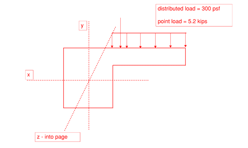
So for the cantilever, I can simply use the basic moment and shear formulas, and reinforce the tension side accordingly.
- Another option I am considering is to consider the cantilever as a corbel per ACI 318-19 and analyze it for shear friction? Should I consider the cantilever as a true cantilever or as a corbel? Or, should I just select the more conservative approach?

Regarding the rectangular section part of the beam, all the loads are on the cantilever. As a result, should I design it as a rectangular beam, with all moments from the cantilever occurring about the Z axis? So I would have to use the section corresponding to the Z axis, correct?

Thanks for your time.
 
Replies continue below

Recommended for you

If this section is spanning from A to B along the Z axis, there will be bending moment about the X axis and torsion about the Z axis. Design accordingly.

The load "out on the slab" can be replaced by a concentric load at Y and a torsional moment about the Z axis.


JAE, thanks for your feedback.

I understand resolving the concentric load to the Y Position and then including a torsional moment about the Z axis. Yes, the beam spans from point A to point B along the Z axis.

What I don’t understand is the moment about the X axis. Do I calculate that based on the resolution of the eccentric point load and area load to the Y position of the beam?
 
Hopefully I'm not misunderstanding you on this but you would take that uniform load on the flange and convert it to a concentric point load on the main beam, located at the Y axis, assuming the Y axis is located at the centroid of the beam cross section. This PSF load would become a lb/ft. load along Z.

The point load you would simply move to the Y axis. I'm assuming the point load is a single concentrated load at some point along the span.

This gives you a lb/ft on the beam which you would use to calculate the X moment (simple span = wL^2/8).

The torsion load would be a combination of a uniform torsional force applied along the span due to the uniform load in addition to a single torsional load applied at a point on the span.
The beam would have a torsional diagram comprised of both of these torsional forces.

The uniform load (times its eccentricity to Y) creates that uniform load that results in a torsional diagram looking much like a standard shear diagram (like a bow tie).
The concentrated load (point load times its eccentricity to Y) would be a block shear type diagram, similar to a shear diagram caused by a point load on a span.
You then combine the two diagrams into a single torsion diagram along the span.

The torsion would be then calculated from A-B creating a shear-like torsion diagram, maximum at the ends (assuming the beam is torsionally fixed at the ends).

Hope this answers your question.

 
Status
Not open for further replies.
Back
Top