Continue to Site

Eng-Tips is the largest engineering community on the Internet

Intelligent Work Forums for Engineering Professionals

  • Congratulations KootK on being selected by the Eng-Tips community for having the most helpful posts in the forums last week. Way to Go!

Conceptual Question regarding design of "L-shape" reinforced concrete beam

Status
Not open for further replies.

gmoney731

Structural
Oct 24, 2018
32
Hello. I am trying to analyze an existing beam for the following load conditions. The beam section is an "L shape".
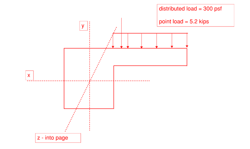
sketch_nav7mg.png


So for the cantilever, I can simply use the basic moment and shear formulas, and reinforce the tension side accordingly.
- Another option I am considering is to consider the cantilever as a corbel per ACI 318-19 and analyze it for shear friction? Should I consider the cantilever as a true cantilever or as a corbel? Or, should I just select the more conservative approach?

Regarding the rectangular section part of the beam, all the loads are on the cantilever. As a result, should I design it as a rectangular beam, with all moments from the cantilever occurring about the Z axis? So I would have to use the section corresponding to the Z axis, correct?

Thanks for your time.
 
Replies continue below

Recommended for you

If this section is spanning from A to B along the Z axis, there will be bending moment about the X axis and torsion about the Z axis. Design accordingly.

The load "out on the slab" can be replaced by a concentric load at Y and a torsional moment about the Z axis.


JAE, thanks for your feedback.

I understand resolving the concentric load to the Y Position and then including a torsional moment about the Z axis. Yes, the beam spans from point A to point B along the Z axis.

What I don’t understand is the moment about the X axis. Do I calculate that based on the resolution of the eccentric point load and area load to the Y position of the beam?
 
Hopefully I'm not misunderstanding you on this but you would take that uniform load on the flange and convert it to a concentric point load on the main beam, located at the Y axis, assuming the Y axis is located at the centroid of the beam cross section. This PSF load would become a lb/ft. load along Z.

The point load you would simply move to the Y axis. I'm assuming the point load is a single concentrated load at some point along the span.

This gives you a lb/ft on the beam which you would use to calculate the X moment (simple span = wL^2/8).

The torsion load would be a combination of a uniform torsional force applied along the span due to the uniform load in addition to a single torsional load applied at a point on the span.
The beam would have a torsional diagram comprised of both of these torsional forces.

The uniform load (times its eccentricity to Y) creates that uniform load that results in a torsional diagram looking much like a standard shear diagram (like a bow tie).
The concentrated load (point load times its eccentricity to Y) would be a block shear type diagram, similar to a shear diagram caused by a point load on a span.
You then combine the two diagrams into a single torsion diagram along the span.

The torsion would be then calculated from A-B creating a shear-like torsion diagram, maximum at the ends (assuming the beam is torsionally fixed at the ends).

Hope this answers your question.

 
Status
Not open for further replies.

Part and Inventory Search

Sponsor