Continue to Site

Eng-Tips is the largest engineering community on the Internet

Intelligent Work Forums for Engineering Professionals

  • Congratulations waross on being selected by the Eng-Tips community for having the most helpful posts in the forums last week. Way to Go!

Concrete Beam Repair

Status
Not open for further replies.

SteelPE

Structural
Mar 9, 2006
2,743
I have a project that is currently under construction that I designed over 4 years ago.

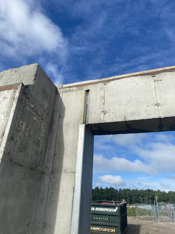
In the infinite wisdom of the foundation contractor, they decided to install a contraction joint at the end of a concrete beam in a foundation wall at the location we have a integral concrete beam.
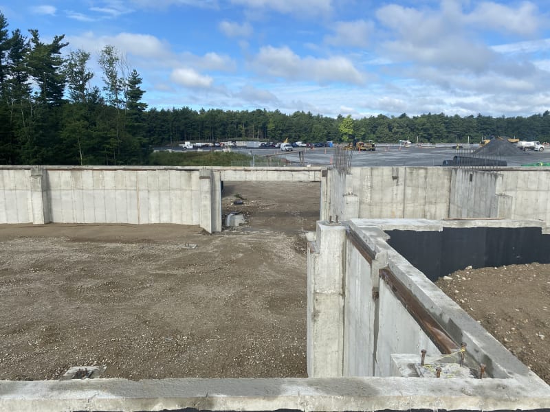
IMG_3877_e3hyev.jpg


IMG_3880_zfmm9s.jpg


This beam is supporting:

-The weight of the beam itself
-5'-0" of first floor retail space
-building façade (metal studs and efis)
-a catwalk on the outside of the building.

Now I am left to wonder what is going to happen with regards to shear in this area. The foundation contractor said he installed a contraction joint here because he thought that the wall was going to crack there and that was the best area for the crack to form...... but he forgot that we had a ton of reinforcing running though the beam here )4-#8 bars top and bottom with #3 ties/stirrups at 10" o.c.).

How do we go about repairing this beam?
 
Replies continue below

Recommended for you

What does the section look like through that joint? Is it the original beam and wall reinforcement detailing just with a chamfer strip essentially eating into the concrete cover at that section?
 
As far as I know, they placed all of the intended reinforcing

4-#8 top
2-#8 mid/skin
4-#8 bottom

with #3 ties at 10" o.c.

Beam is 2'-2" tall x 16" wide

So yes, the chamfer is just eating into the concrete cover and reducing the concrete shear capacity.... but there is now a vertical shrinkage crack that has formed through the wall here.

 
I haven't read this too much in detail, but would a precast lintel or a site cast replacement or a steel beam on a bearing plate be workable?
 
If there is a concern about a reduced concrete shear capacity - my first thought would be to provide a new supporting element to the opening side of the beam. Can you sneak in a HSS steel column at that location?
 
Is there enough shear capacity? (Bear in mind that a vertical plane is effectively a shear friction check, not a regular shear check).

If the shear works I’d be reinstating the cover somehow.
 
Yes, I agree with the shear friction check. I’m pretty optimistic that the numbers would work out, given it’s a monolithic joint.

Another thought: You could do an injectable epoxy repair to fill the shrinkage crack, followed by a repair mortar to fill in the chamfer.
 
What would you have done there if the crack occurred in that location without the contraction joint? Though it should have been a diagonal crack away from the corner most likely. Just based on proportioning, my gut says there should be lots of capacity for shear friction and the beam would fail in flexure first, but I'm curious to know how the numbers turn out.
 
Not a lot of load. Maybe a steel bearing seat bolted to the column. In my opinion, better than relying on shear friction, but then I don't rely on shear friction, period.
 
Based upon this discussion and what I can figure we have a demand of:

Vu = 31 kips

Of we use shear friction with saying the concrete was cast monolithically (mu = 1.4) and normal weight concrete.

1-#8 bars will provide a shear friction resistance of phi Vn = 49.8 kips.

We have a whole bunch of #8 bars (4 top, 4 bottom and 2 each face as skin reinforcing) then I am guessing we are OK for shear then.
 
Just have to make sure you have adequate development length on each side of the section.
 
Why is this thing 2'-2" deep and 16" wide with so little load on it in the first place?

The skin reinforcement is there because it's so deep, correct?

And the stirrup spacing....?
 
lex,

Probably because it goes from the top of the opening to the top of the wall. The dimension happens to be 26".
 
Something using shear friction can also take flexure (i.e. tension/compression)? I didn't know that. I guess it's similar to structural steel in this way. I'm just used to having separate shear friction dowels. But if it works, it works.

Personally, I'd add some kind of ledger angle or WT seat or something at the bottom to take at least 50% of the shear. Main reason is to "punish" the contractor for doing this, but secondary reason is for peace of mind due to an unconventional shear connection.
 
Punish the contractor... Trying to stay out of the mud, but I can't sat that didn't cross my mind. If I'm going to believe in brackets and bolting to the existing concrete using post installed anchors then I might as well believe in shear friction. I am going to push for adding a column to be installed..... something small that can be welded to the embedded steel jamb. We have a meeting this morning with the Arch.

I have 10-#8 bars in the beam as outlined above. I wanted to make this as simple for the foundation contractor as I could. Really the bottom 4 bars are not doing much at this joint.... and neither are the "skin" bars. But it is good to have them in place for this purpose.

In regards to why this beam is even there if the load is so light. First, I don't think a 31k end shear is light. Second, hokie66 got it right, this is a building with underground parking. We merely put an opening in the perimeter foundation wall to allow for the vehicles to enter and exit the parking area. The geometry of the beam was determined by the foundation for the building. To ease confusion by the contractor, we didn't vary the wall thickness in this area.
 
SteelPE said:
If I'm going to believe in brackets and bolting to the existing concrete using post installed anchors then I might as well believe in shear friction.

If the contractor had omitted the beam entirely, or if this was renovation project - surely most of us would come up with a drilled and epoxy'ed solution for the beam.
 
I agree with EZBuilding. If this beam was omitted, I'd epoxy something into place and design the beam conservatively as pin-pinned. For non-pinned condition, the embedment I'd use would be enough to develop a tension splice, which is nearly impossible for #8, but it has been accomplished here. So in pretty much every aspect, I think this connection works.

It's just a matter of doing something so that people don't repeat this mistake in the future, and for protecting the integrity of good construction and design. It just happened to work in this case, but it's not always going to work. And if you don't do something, the optics are that you're basically admitting that you overdesigned it (which you didn't).
 
Status
Not open for further replies.

Part and Inventory Search

Sponsor