Eng-Tips is the largest engineering community on the Internet

Intelligent Work Forums for Engineering Professionals

Concrete Column Transitions - Bearing Area

Status
Not open for further replies.

MattyG123

Structural
Mar 12, 2020
7
0
0
AU
Hi All,

Had a question regarding Column Transitions like the below.

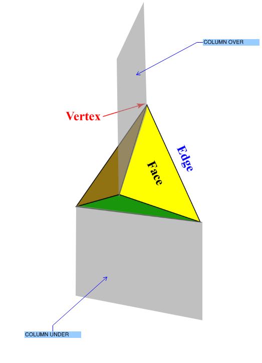
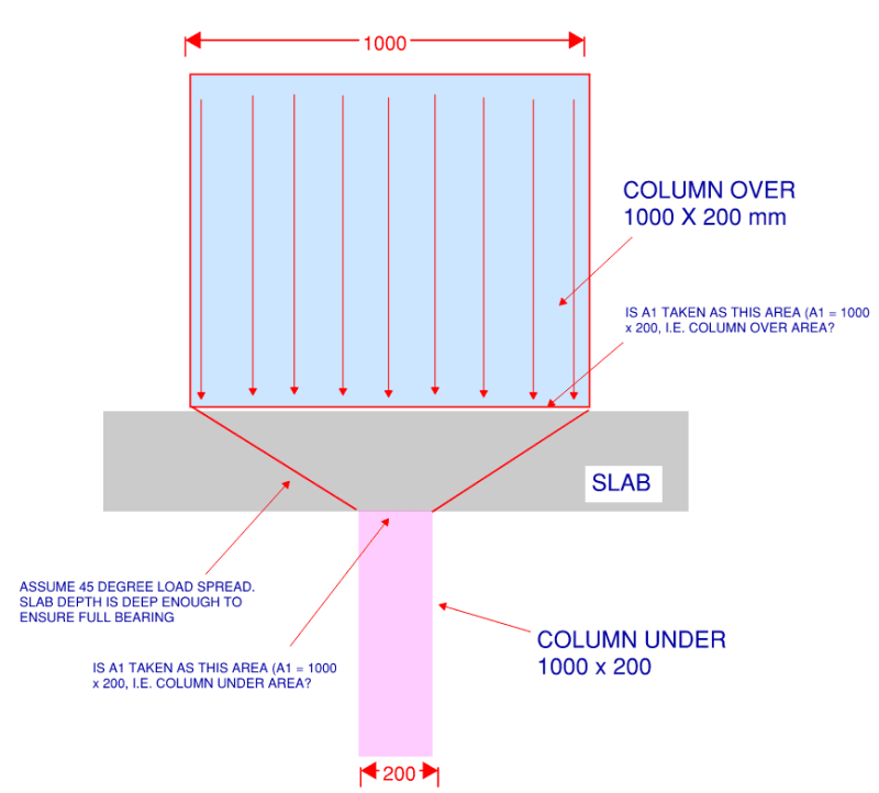
If we have a column over (1000 x 200) and column under (1000 x 200) but rotated and we wanted to check Bearing.

I've been advised to check the bearing of the slab (Top and Bottom of Slab) as this is usually lower in concrete strength.

Questions

1. Is the A1 area correct?
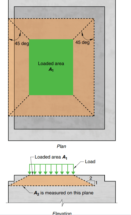
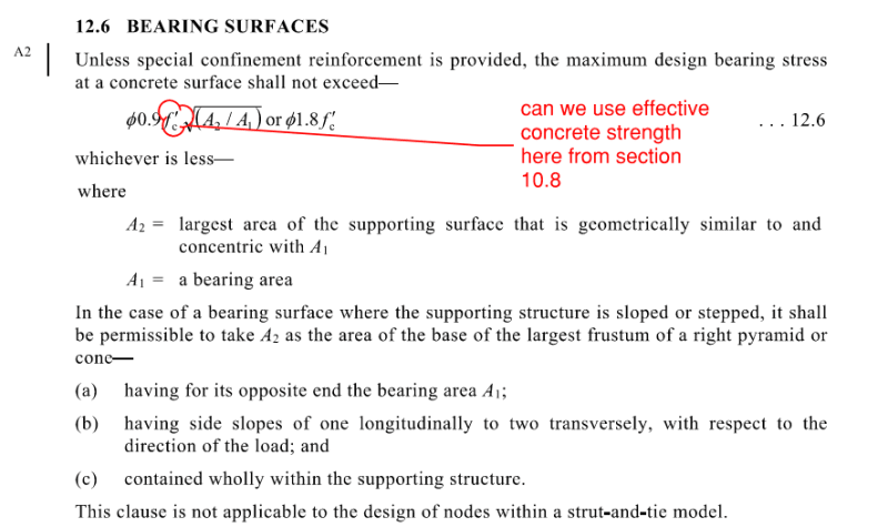
2. What can I take as A2 to increase bearing capacity as this is slightly confusing. And it needs to be geometrically similar to and concentric with A1 as per Section 12.6?
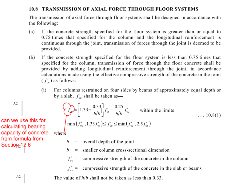
3. Can we use the effective concrete strength from the below in AS3600 (Section 10.8) to increase Bearing capacity in the formula for Section 12.6?

Capture_oyetus.png

Capture1_yo7khv.png

Capture2_zpkpbk.png
 
Replies continue below

Recommended for you

When I have performed similar checks - I have utilized A1 as the overlapping areas between the two column, for your example this would equal 200 x 200. Accordingly for the bearing check - I would not provide for an increase in capacity due to a larger supported area - I see this more in a condition where a column is supported by a foundation that is wider than it on all sides.

 
Agree with EZ building, your area is 200X200.

You fan out at a ratio of 2 horizontal to 1 vertical.
You cannot fan out in one direction but not the other.

Screenshot_2024-05-14_081947_tbydqg.png
 
Taking A1 as the overlapping area and A2 at mid depth of the transition element (slab, beam or drop cap) is also what I do and I believe it's the right approach
The key is that A2 must be "geometrically similar" (same shape and aspect ratio) and concentric to A1.
In this situation, for dispersion I normally use a more conservative 45deg (1:1) angle, not the 1:2 proposed in the code.
Obviosuly the transition element must be large enough to be able to fully include the assumed A2.
The other important aspect is that the column above and below must be designed for any eccentricity equal to the distance between the column centroid and the A1 centroid. Horizontal reinforcement must also be designed to account for the strut-tie due to the stress concentration in the column and the stress dispersion in the transition element.
 
This is a strut-and-tie problem every day of the week. The bearing stress issue is just one small thing that could go wrong with that kind of detail.
 
I agree with the comments above that in terms of a code check that A1 = 200x200 and A2 is the fanned-out area at mid-slab depth, equating to 400x400, assuming a 45-degree fan.

I don't mind this arrangement, providing it passes those bearing checks. In reality, apart from the codes ideas about "geometrically similar areas", you can get a nice tetrahedron (4 side dice shape) compression block form within the slab:

COLUMNS_wrairy.jpg
 
I don't have a problem with this being more than 200 × 200. In the plane of the top wall the forces are going inwards on the bottom wall so the possibility of bursting the bottom wall out of its plane seems unlikely to me. In the other direction it's the other way around, top wall is compressed laterally inwards so it's also fine. Tension should be along the length of both walls which should not be a huge problem.
It makes no sense to me to check it at the middle of the slab, where is this coming from? I agree with slickdeals, I'd go with: 200 x (200 + slab thickness).
 
The idea of checking the middle is that the 200x200 fans down from the column above and fans up from the column below, meeting in the middle.
 
Oh, ok... your previous picture does not show that, right? That solution would have 4 more edges if I can visualize it correctly.
I really don't like this idea. It's a very messy system of spatial struts that are hard to visualize and the meeting point of the struts at mid height is held from bursting by the plate - force that simply dissapears and is never checked for. It's probably fine in all the cases, but I like a complete load path solution better.

Another thing that I'm not sure of (someone more experienced with STM can say) in this solution - wouldn't the bottom node also have to be checked, not just the middle one? That bottom node can never get 400mm×400mm.
 
Yes the picture I showed is different to the AS3600 approach. The AS3600 approach is the 200x200 A1 area.

The picture is just what I believe can actually happen, ie a larger part of the column footprint can strut down symmetrically to the column below, as opposed to the AS3600 logic, which requires geometrically similar areas.
 
I'd have no problem with fanning out from the A1 to middle of slab, that is consistent with concrete confinement increasing bearing capacity. I can't see this governing over the nodal stress in a S+T model of the columns, which is spread over only A1.
 
Status
Not open for further replies.
Back
Top