I've hit a road block and would like to hit up the hive mind here at eng-tips to see if anyone has some insight or own thoughts on how to tackle the below issues.
I've got a pretty functional bi-axial concrete section analysis spreadsheet set up for rectangular sections and the Whitney block -
[ I know the Whitney block is unconservative when the compression block has a reduction in area towards the location of peak stress and have formulas derived and verified for linear-constant and the PCA Parabolic-Constant stress blocks so will be adding those sometime in the future, working on the general formula for the EN 1992.1.1.2004 parabolic stress block as defined by equations 3.17 and 3.18 have a formula derived but need to do some verification tests]
Where I am hitting a snag is for asymmetric reinforcement layouts where the entire Mx v My curve skews outside of one of the 4 axis quadrants or lies very close to the P axis at the Tan-1(My/Mx) angle where a P v M slice is desired. Specifically I know that:
[ul]
[li]for some angles no solution may exist because the curve doesn't exist in that quadrant, for these cases I need to determine a good way to find where the P v M slice reaches the P axis. Been messing around with some ways to find this all kind of equally slow at the moment in Excel mostly because I'm trying to do everything with on sheet operations so I can hand check things are getting done correctly offloading most of this to VBA eventually will exponentially speed up the solvers[/li]
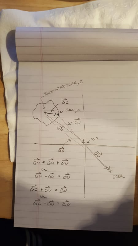
[li]for some angles two solutions will exist because the curve has shifted fully into a quadrant, for these I need to determine some way to do a change of reference on the solution angle so instead of referencing the P,Mx,My origin for angle measurement I need to instead use a coordinate inside the Mx v My slice This is where I'm currently stuck.[/li]
[/ul]
Another option I think may solve both my problems is finding the two peak nominal points and connect them with a straight line and call this the new Z axis then working out the 3D coordinate transformation required to align this new Z' axis with the original Z(axial) axis this should eliminate the two root possibility. I am slowly trying to learn the 3D transformation stuff to attempt this.
Test case to illustrate the problems:
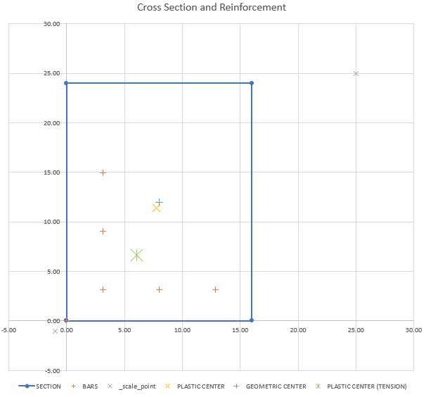
Section and Reinf. (F'c = 5 ksi, 16x24 in, all bars are #8's)
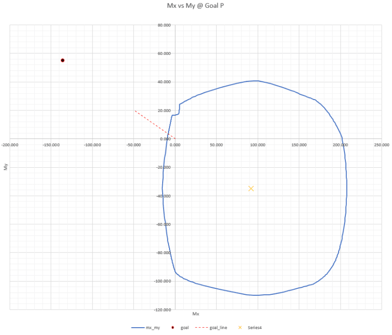
First hurdle curve close to the P axis:
Mx v My slice @ P = -90 kips: Notice curve almost entirely skewed
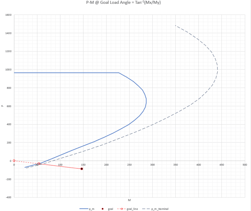
P-M Slice at Tan -1(My/Mx) = 2.7572 radians
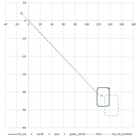
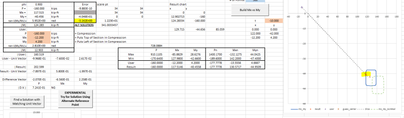
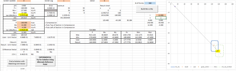
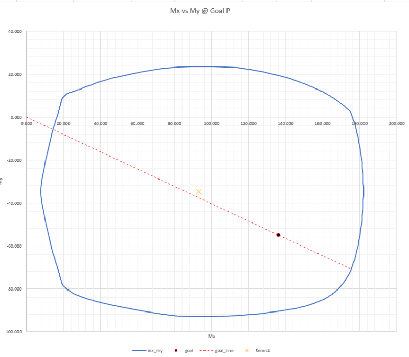
Second Issue Mx My slice completely shifted
Mx v My slice @ P = -120 kips: Notice curve entirely skewed now
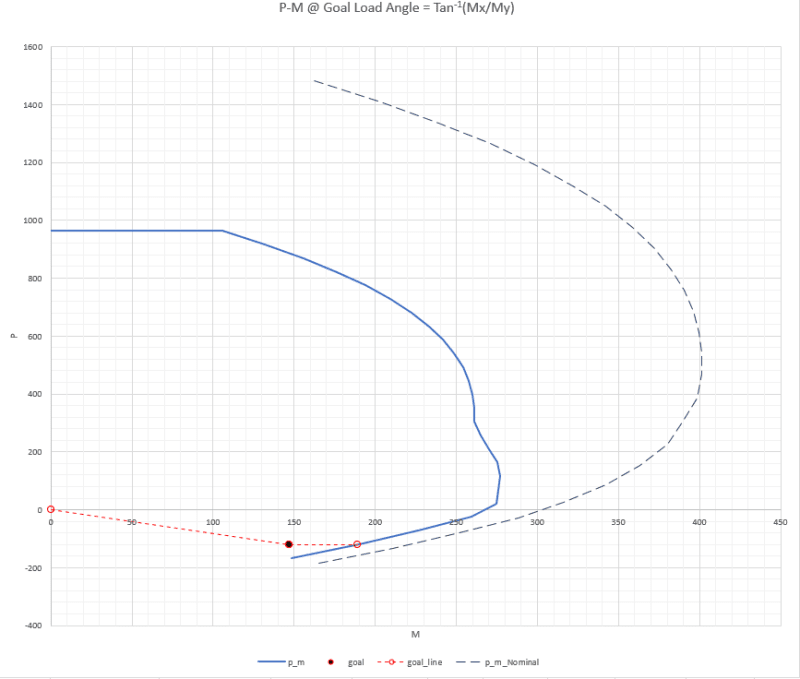
P-M Slice at Tan -1(My/Mx) = -0.384 radians: note curve should actually reach a low point and then have two solutions at most -P's
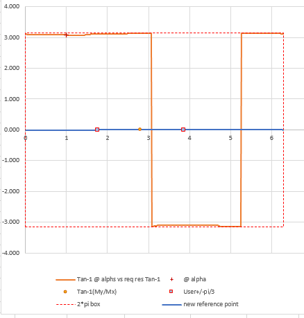
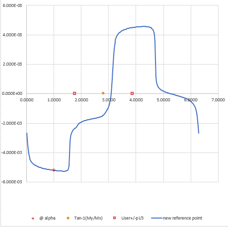
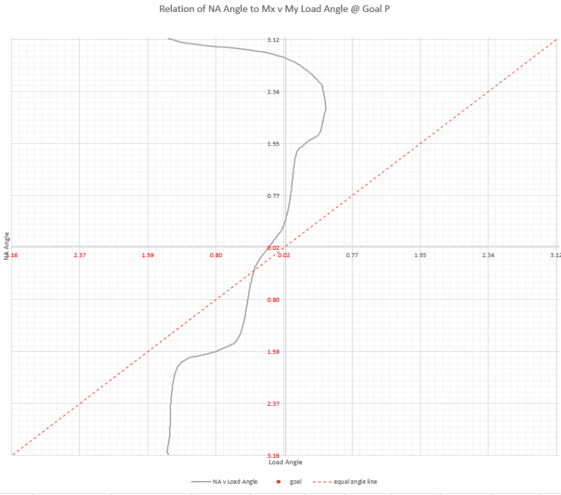
Relationship of the Neutral Axis Angle to the tan -1(My/Mx) load angle at P=-120kips:
This is the chart that best shows that no solution exists for certain load angles
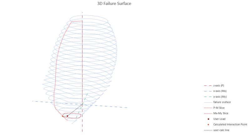
3D Interaction Surface with the Mx/My slice and P-M curve in case it makes the visualization of the problem easier:
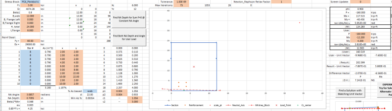
Spreadsheet - Macro Enabled and Required: (link for the curious)
This is very much a work in progress so feel free to ask questions on deciphering what is going on where.
My Personal Open Source Structural Applications:
Open Source Structural GitHub Group:
I've got a pretty functional bi-axial concrete section analysis spreadsheet set up for rectangular sections and the Whitney block -
[ I know the Whitney block is unconservative when the compression block has a reduction in area towards the location of peak stress and have formulas derived and verified for linear-constant and the PCA Parabolic-Constant stress blocks so will be adding those sometime in the future, working on the general formula for the EN 1992.1.1.2004 parabolic stress block as defined by equations 3.17 and 3.18 have a formula derived but need to do some verification tests]
Where I am hitting a snag is for asymmetric reinforcement layouts where the entire Mx v My curve skews outside of one of the 4 axis quadrants or lies very close to the P axis at the Tan-1(My/Mx) angle where a P v M slice is desired. Specifically I know that:
[ul]
[li]for some angles no solution may exist because the curve doesn't exist in that quadrant, for these cases I need to determine a good way to find where the P v M slice reaches the P axis. Been messing around with some ways to find this all kind of equally slow at the moment in Excel mostly because I'm trying to do everything with on sheet operations so I can hand check things are getting done correctly offloading most of this to VBA eventually will exponentially speed up the solvers[/li]
[li]for some angles two solutions will exist because the curve has shifted fully into a quadrant, for these I need to determine some way to do a change of reference on the solution angle so instead of referencing the P,Mx,My origin for angle measurement I need to instead use a coordinate inside the Mx v My slice This is where I'm currently stuck.[/li]
[/ul]
Another option I think may solve both my problems is finding the two peak nominal points and connect them with a straight line and call this the new Z axis then working out the 3D coordinate transformation required to align this new Z' axis with the original Z(axial) axis this should eliminate the two root possibility. I am slowly trying to learn the 3D transformation stuff to attempt this.
Test case to illustrate the problems:
Section and Reinf. (F'c = 5 ksi, 16x24 in, all bars are #8's)
First hurdle curve close to the P axis:
Mx v My slice @ P = -90 kips: Notice curve almost entirely skewed
P-M Slice at Tan -1(My/Mx) = 2.7572 radians
Second Issue Mx My slice completely shifted
Mx v My slice @ P = -120 kips: Notice curve entirely skewed now
P-M Slice at Tan -1(My/Mx) = -0.384 radians: note curve should actually reach a low point and then have two solutions at most -P's
Relationship of the Neutral Axis Angle to the tan -1(My/Mx) load angle at P=-120kips:
This is the chart that best shows that no solution exists for certain load angles
3D Interaction Surface with the Mx/My slice and P-M curve in case it makes the visualization of the problem easier:
Spreadsheet - Macro Enabled and Required: (link for the curious)
This is very much a work in progress so feel free to ask questions on deciphering what is going on where.
My Personal Open Source Structural Applications:
Open Source Structural GitHub Group: