Continue to Site

Eng-Tips is the largest engineering community on the Internet

Intelligent Work Forums for Engineering Professionals

  • Congratulations KootK on being selected by the Eng-Tips community for having the most helpful posts in the forums last week. Way to Go!

Concrete drilled piers supporting retaining wall

Status
Not open for further replies.

skimboard20

Structural
Mar 10, 2021
19
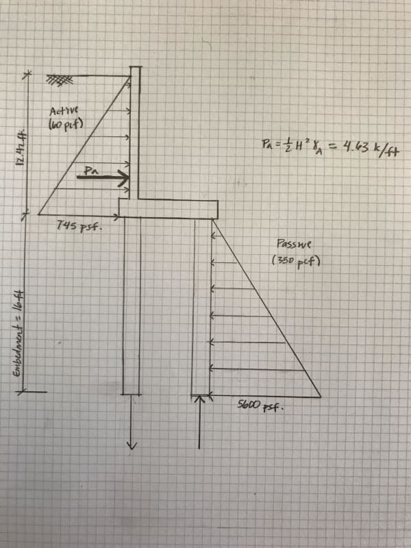
I am designing a foundation system on a steep slope in CA where one basement wall needs to retain about 12 ft of soil. Instead of having one huge drilled pier to resist the lateral earth pressure and induced moment, I am trying to design a paired pier system, where the lateral load is resisted by the passive pressure behind the pier, and the induced moment by the active pressure is decoupled into forces that are resisted by the piers' skin friction.

I am wondering if anybody else would approach the design this way, and if its even feasible to develop resistance in this manner. Is there a more efficient way to think about this design?

I've attached a section of the wall and pressure diagrams.

Thanks!
wall_section_ll4uhh.jpg
 
Replies continue below

Recommended for you

I've done this and believe it to be an efficient solution in certain situations. The design gets a bit tricky in that the base and, to a lesser extent, the wall really become two way spanning elements rather than simple 2D structure. So punching shear, distribution steel etc. Like you, I do the single row of piles whenever I can justify that. In the right soils, and at the right scale, a similar thing with helical piles can be fairly efficient. Those, potentially, an even be battered for shear resistance. That said, I don't supper love battered for high seismic.
 
How would you excavate the basement? Soldier piles? If you need to do soldier piles for excavation then I would use permanent shoring piles. 12ft retaining height is not much to see the difference in pile size between one row and two rows of piles. Check with the pile/drilling contractor to see what they prefer.
 
Design the wall, then the piles. Don't design them together.

Once you have the preliminary pile reaction forces, study a book on pile design (horizontally loaded piles), then consult with the geotechnical engineer. You should probably know the difference between long, short, and intermediate piles before proceeding.

...Also don't forget allowable wall deflections and global slope stability while designing.

 
I appreciate the insight, Waxwing. I have done a little research on piles, but only enough to get to this point.

hotmailbox, since it's such a steep slope, they only need to excavate a couple feet to drill the piers. But they will backfill behind the wall up to 12 ft to create a flat grade at the floor above.

KootK, thanks for the validation. I guess I am running into the issues you mention. In a 2D section, the forces resolve quite easily. But when I start thinking about the retaining wall spanning between piers, I'm thinking the grade beam is in torsion. My only thought is to add flexural reinforcement in the grade beam above the pier at the toe...


Will you provide a sketch , a section showing the basement floor, size of the bldg etc? ..
If this is for basement storey of a bldg at steep slope , you could prefer a mat foundation with thickened thk. at high level side.

I used similar concept for an access ramp for car parking at the basement storeys. But in my case, the ht was around 30 ft . I preferred the heel piles shorter and staggered.

Regarding the modelling, you preferred to use γs= 350 pcf implies Kp=3.0 .. However, since the piles having circular shape, the passive thrust is almost half of the plain surface. Moreover, i think modelling the passive side with horizontal springs is better . Ask to geotech. group for passive spring constant and how varies with depth.


HTURKAK, just curious, what is the rationale for the shorter and staggered heel piles?

The section in my original post describes the retained height for the basement. I would keep in mind that this is only a two story house, so the loads above are not that substantial.

The geotech provided the guidance of 350 pcf and passive spacing of 1.5 x diamter of piles (16 inches in this case).
 
My lingering question is if I can truly rely on the piers to be in tension and compression to resist the overturning of the active pressure? Or if I need to design the piers to have adequate flexural capacity?
 
You definitely have to design piers for bending because all soils loads will be supported by piers at the top and fixity points of piers are way down below the basement level considering the down slope.
 
I would not use the passive pressure and the height of the pile. What you really need to get is a "horizontal modulus of subgrade reaction" from the geotech. Use that value with the projected area of the pile and you end up with a bunch of springs over the height. Analyze this pile in a 2D analysis program that has the ability to handle springs. This will generate a shear and moment diagram for the piles, which should be used in the design of the piles.
 
For the lateral resistance of the piles, I would recommend using a P-y based program, such as Allpile or LPile.

If you are able to excavate for even a small heel on the footing, it would likely yield significant benefits in reducing the loads on the piles, particularly in uplift loading on the back row piles.

Rod Smith, P.E., The artist formerly known as HotRod10
 
I do not have access to Lpile or Allpile. I can do some pier design in RetainPro, and I can find the flexural demand of the piers in Shoring8, but that's what I'm working with right now.

Appreciate the insight everyone.
 

Hi skimboard,
Pls find below my responds specifically mentioning my nickname;

- The passive thrust calculation in your model is valid for continuous piling , sheet piling etc. in your case the pile spacing for the front row ,should be in the range of 8 ft . The second row piling (under the heel ) will not be so effective to get passive thrust if not staggered.

- You say ' only a two story house, so the loads above are not that substantial.' But the DL of bldg still will help to resist overturning and sliding .

- I assume 16 in. is the diameter. so the spacing should be min. 3X D =4 ft.

Before softwares, Point of Fixity concept were used to calculate the lateral resistance ( max. moment and shear ) and the lateral deflection. But not PASSIVE THRUST concept which could be applicable for sheet piling etc...


I will suggest you to analyze your model with FEM or use P-y based program as BridgeSmith suggested . If you provide a sketch showing the slope, section of the proposed bldg with dimensions you could get better responds..
 
- I assume 16 in. is the diameter. so the spacing should be min. 3X D =4 ft.

At that spacing, depending on the depth, there could be some overlap of the resisting soil, and therefore some reductions in side friction for uplift and bearing. The AASHTO LRFD has reductions up to 5D spacing for some soils and depth/diameter ratios.

Rod Smith, P.E., The artist formerly known as HotRod10
 
Status
Not open for further replies.

Part and Inventory Search

Sponsor