NRam
Structural
- May 5, 2022
- 6
Hi all,
Struggling conceptually with understanding this issue. So I have a few questions.
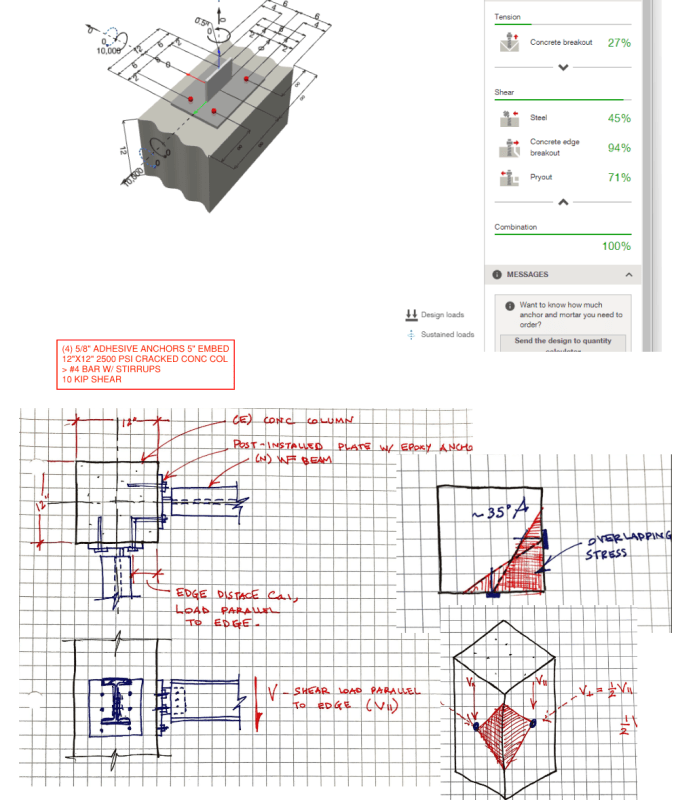
See attached document and images for the background.

1. Where does the V_parallel = 2V_perpendicular provision from ACI 318-19 Section 17.7.2.1c come from?
2. What would you consider a safe interaction equation or methodology?
How would you tackle this issue, and what load would you design the anchors for?
In advance, thank you!
Struggling conceptually with understanding this issue. So I have a few questions.
See attached document and images for the background.

1. Where does the V_parallel = 2V_perpendicular provision from ACI 318-19 Section 17.7.2.1c come from?
Even in the commentary, the code merely states
"The maximum shear that can be applied parallel to the edge, V||... is twice the maximum shear that can be applied perpendicular to the edge."
This seems somewhat arbitrarily chosen. What's the mechanism here??
I've seen some posts discussing this that merely state that it ought be checked. But does anyone know the rationale behind it?
2. What would you consider a safe interaction equation or methodology?
a. Would you consider them completely independently? This approach seems unreasonable to me. The stresses would combine in someway.
b. Would you consider a linear interaction? Meaning Vd/Vc + Vd/Vc > 1
b. Would you consider a linear interaction? Meaning Vd/Vc + Vd/Vc > 1
This to me seems more reasonably, and what I would design for, but could result in over conservatism.
This would require each embed above to be below 50% capacity.
This would require each embed above to be below 50% capacity.
How would you tackle this issue, and what load would you design the anchors for?
In advance, thank you!
