Continue to Site

Eng-Tips is the largest engineering community on the Internet

Intelligent Work Forums for Engineering Professionals

  • Congratulations KootK on being selected by the Eng-Tips community for having the most helpful posts in the forums last week. Way to Go!

Concrete edge (breakout) failure in shear on anchor group - Eurocode 1992-4 vs ACI 318 2

BridgeEngineer21

Structural
Oct 26, 2021
56
I am working on an anchorage design in accordance with Eurocode. In cases where Eurocode is unclear, I can refer to other sources, and in extreme cases I can apply for a waiver of a code requirement if I have a good justification to do it an alternate way. So, here is the situation at issue:
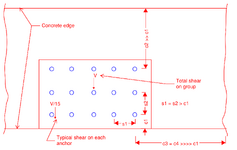
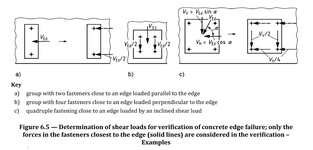
1732877519515.png

The relevant Eurocode clauses for concrete edge failure:
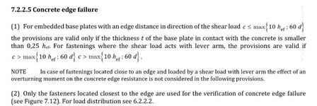
1732877334754.png
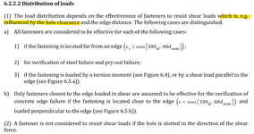
From 6.2.2.2:
1732877376129.png

I think its pretty clear Eurocode requires me to check this edge failure area against the full shear force:
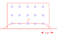
1732877584661.png
Now if I look at ACI, this situation would warrant the following 2 cases to be checked:
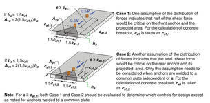
1732877665881.png
1732877748437.png

Clearly, the Eurocode check is much more conservative, and in this case is causing serious problems.

Now, I'm also referring to a very helpful reference book: Anchorage in Concrete Construction, First edition (R. Eligehausen, R. Mallee, J. F. Silva). I don't know the history exactly, but it seems that a lot of the research and explanations adopted in this document are incorporated in both Eurocode 1992-4 and ACI 318. (In general, ACI seems to more explicitly state some of the explanations and reasoning from this reference in the commentary column).

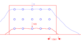
I'm sharing a couple of pages attached in case anyone is interested in some more reading, but essentially the book agrees with the ACI reference manual. This figure below is particularly illustrative, and this part of the text was persuasive to me: "If the shear load is initially resisted by the near-edge anchor alone, it will generate a concrete breakout crack. Following displacement sufficient to bring the rear anchor into a bearing condition, that anchor will then resist the entire shear load.
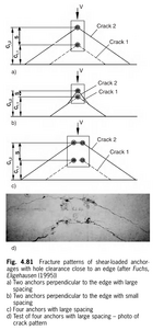
1732878480942.png

Now, the question I have for all of you is if you can think of a persuasive argument why the Eurocode assumption on shear distribution should be adopted over the ACI/reference manual assumption, other than "just cause" it's more conservative.

Appreciate any input!
 

Attachments

  • Pages from Anchorage in Concrete Construction, First edition (R. Eligehausen, R. Mallee, J. F....pdf
    190.9 KB · Views: 5
Replies continue below

Recommended for you

Do you even need those anchors close to the edge for ultimate shear strength?

All they seem to be doing according to Eurocode as you describe is weakening the configuration.

I won't claim expertise in this by progressive failure does seem a risk. The assumption that all bolts share load approximately equally works great for steel on steel when there is good ductility but the assumption can break down for less ductile materials.
 
Clearly, the Eurocode check is much more conservative, and in this case is causing serious problems.
I am not sure for this interpretation . Acc. to my past experience , the edge failure is the less probable scenario and you are free to use without hole clearance application . If you have hole clearance , yes.. you are expected to check edge failure for the worst case scenario.
If this is a real case and the edge failure governs , you have some other options ;
- You may provide supplementary reinf.
- You may consider to mobilize all of the anchors with filling the hole clearance,


1732960563164.png
 

Attachments

  • FINAL_fischer_Whitepaper (2).pdf
    5.4 MB · Views: 6
Do you even need those anchors close to the edge for ultimate shear strength?
Not for shear, but there is also a significant bending moment on the connection that necessitates the three rows of bolts

All they seem to be doing according to Eurocode as you describe is weakening the configuration.

I won't claim expertise in this by progressive failure does seem a risk. The assumption that all bolts share load approximately equally works great for steel on steel when there is good ductility but the assumption can break down for less ductile materials.
Isn't the progressive failure assumption basically the ACI approach though? Eventually you're left with the rear bolts resisting the full load. Whereas the Eurocode approach (at least as I interpret it) is basically to ignore anything past the edge row of bolts, and if that can't resist the full load, then you've failed.

I guess the Eurocode approach could be seen as a way to force a lower threshold until you need to call for supplementary reinforcement. But I am having issues with the supplementary reinforcement itself, which is why I returned to the original edge failure check to see if I could reason my way out of the edge failure to begin with. Was planning to bring up my issues with that as a second question after this discussion got going but maybe I'll introduce them now...
 
...Basically, the shear forces on this connection are quite high, the geometry is very constrained (I can't change the bolt group layout at all), and the bolted item is a temporary construction attachment into a wall that's heavily congested with permanent reinforcement. The anchor embedment length is around 800mm, the edge distance to the front face is about 250mm, and the spacing in both directions around 400mm.

The preliminary design assumption was that supplementary reinforcement can be provided along the entire length of the anchor. Eurocode is silent about spacing of the supplementary bars in the vertical dimension, only giving requirements for the bar size and the horizontal clearance between bar and anchor to be as minimal as possible. So from a purely code compliance standpoint, this designseems acceptable.

But, then I turn to ACI and the same reference text I mentioned above. Per the reference text: "If the hairpin is positioned away from the surface of the concrete, larger deformations of the stud are required to activate the hairpin. According to the limited experimental investigations of Ramm, Greiner (1991) the failure load associated with this geometry decreases as much as 30%, depending on the edge distance, if the hairpin is positioned at a depth of 50 mm rather than with normal concrete cover."

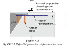
And per ACI R17.5.2.1:
1733083630389.png

This makes it clear that really only the uppermost bar, maybe 2 or 3 bars at most should be counted. The figure from ACI makes clear why - bars lower than that are not sufficient anchored into the failure plane to provide much help. In fact, in my specific scenario with hef >> cover, many of these supplementary bars won't cross the failure plane at all.

Now again, the total shear force is high, so when converted into tension in the supplementary reinforcement the original design called for 12 layers of supplementary bars (24 legs total) along the length of the anchors. Given the size restriction on these stirrups, there's just no way to make it work only considering the top layer. Same issue if we try to count on supplementary surface reinforcement rather than stirrups.

Putting aside code compliance issues, do you all agree with my interpretation of ACI (and the reference text) that only the uppermost bar(s) should be counted? And do you agree with this requirement, or see any reason why it would have been omitted from Eurocode?
 
HTURKAK, appreciate your input as always. I would like to just ask a few clarifications to your comment.
I am not sure for this interpretation . Acc. to my past experience , the edge failure is the less probable scenario
What do you mean by this exactly? Edge failure is less probable than what?
and you are free to use without hole clearance application . If you have hole clearance , yes.. you are expected to check edge failure for the worst case scenario.
Do you mean to say that if there is no hole clearance, then you can just ignore edge failure? I don't have Eurocode in front of me until I go to work tomorrow, but if that's there then I must have missed it. My anchors are cast-in, so I don't think there would be any hole clearance?
If this is a real case and the edge failure governs , you have some other options ;
- You may provide supplementary reinf.
Please take a look at my post above on supplementary reinforcement, I'd be interested to hear your opinion on this with your experience.

- You may consider to mobilize all of the anchors with filling the hole clearance
But isn't this just the ACI method then? Assume all the anchors can be mobilized and take the outer failure plane from the rear anchor row? Doesn't it contradict the requirement of Eurocode 7.2.2.5(2) above?
 
The outer row of anchors can end up taking all the shear load due to bolt misalignment and lack of ductility in the connection. By the time the other bolts have engaged the first crack has formed. Crack 1 can carry the entire load so it’s worth assuming it does. Alternatively filing all the holes ensures the load is shared across all anchors, if you want to take that approach.
 
Not sure if I get what you mean by "filling all the holes". If the bolts are all cast-in, shouldn't all the holes be "filled" with direct engagement between anchors and concrete?
 
By holes I’m referring to the annular gap. If you have anchors welded to a plate then there is no hole, and it’s not an issue.
 
Ah, understood. If the gap between the plate and bolts is filled sufficiently to ensure no clearance, do you think it could be justified per Eurocode to share the load to all bolts then? The highlighted line seemingly implies that they acknowledge it makes a difference, but they don't explicitly state that again:

1733128715193.png
 
Yes, the Eurocode in that clause is implying that you can share the load to all anchors. Look up fib Bulletin 58 if you are after resource showing how to design for multiple anchors to be effective. The method is generally referred to in the literature and standards as shear resisted by the back anchors, which can be achieved as noted above by others when you eliminate the annular gap between anchor and baseplate such that you can ensure all anchors are effective in resisting shear. The fib guide has an in depth discussion. There are drawbacks to the method - the guide limits its applicability to (from memory, double check this) 3 rows of anchors perpendicular to direction of shear. Another consideration is that if your crack propagates from the back anchors then theoretically all the anchors below that will be ineffective at ultimate limit state as they are embedded in the dislocated piece of concrete, so all your shear (in terms of steel shear capacity of the anchors) will be put through the back anchors only. Pryout is calculated similarly based on a reduced tension cone area.

In terms of supplementary reinforcement if you use the simplified strut and tie method described in the Eurocode you don't have the 0.5 reduction factor that they introduce to allow for the gap between hairpins and anchors which will get you more capacity. To me it looks like filling the holes plus supplementary reo looks like the way to go. Regardless of the code restrictions spreading your shear over a wider area by having the filled holes will enable you to engage more supplementary reo. Don't forget to account for the shear eccentricity in determining the tension in your supplementary reo, there are formulas for this in the Eurocode.

In terms of shear distribution for your plate you will not usually get uniform shear distribution (the V/15). If you have a cleat or something introducing the load the middle columns are always more highly loaded. I'd even suggest investigating whether you need the bottom row of anchors - 15 is quite a lot. You could test the connection without them in order to bring the shear further from the edge.
 
Thanks for the great reply icebloom, lots to chew on there. I will respond once I've had the chance to get into it more fully.

Just curious, do you agree with my thought that regardless of the fact that Eurocode doesn't explicitly forbid it, it would not be right to count on hairpin stirrups spaced along the entire anchor bolt?
 

BridgeEngineer21

Do you mean to say that if there is no hole clearance, then you can just ignore edge failure? I don't have Eurocode in front of me until I go to work tomorrow, but if that's there then I must have missed it. My anchors are cast-in, so I don't think there would be any hole clearance?
Dear Bridgeengineer , i do not look to the forum everyday .I am saying that , if there is no hole clearance , the load is shared across all anchors and EC allows this approach as long as if the annular gap is filled or anchor bolt is fixed to the base plate with welding .
The previous posts of icebloom, Tomfh are valuable , great posts and their replies deserve pink stars . ( with new forum interface ,colorless star ).
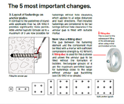
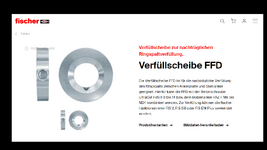
I just want to add , another method is the annular space could be filled with epoxy mortar etc . using filling washer .( this could be viable option for post installed anchors and incase of the use of anchor nuts )

I looked to your internet country code ( DK) . If you know GERMAN ,you may search the web for ( verfüllscheibe )
One of the outcomes ; https://www.fischer.de/de-de/produkte/stahlanker/betonschraube/zubehoer/verfuellscheibe-ffd


1733207445071.png
 
HTURKAK, no problem, I appreciate all your (and everyone else's) input so far. Taken all together I have some thoughts on the possible ways out of this issue, which I've split into 4 options below. I'd appreciate hearing anyone's commentary on the validity of any/all of these options, which you think are feasible or infeasible, or preferable from any other standpoint than my own (I give my preferences and reasoning at the bottom).

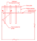
Option 1: In my case I have a base plate which is elevated on top of a hollow structural member which bears on the concrete. So the bolts have a lever arm through the hollow member to the top of concrete. I think either grouting, or using these epoxy washers, is not a feasible solution, because the grout/epoxy will just drip into the hollow opening without some type of formwork in place. So I'm thinking the only way I could ensure no hole clearance in this case is welding all the bolts to the plate. Do you agree? With this option, I would design the supplementary reinforcement as surface reinforcement, as icebloom suggested above, and I can make the connection work. I need to be able to count on the bolt group even if I'm just designing supplementary reinforcement, because if my failure plane starts from the front row of bolts only, there's not enough room for the supplementary reinforcement to be anchored in the failure plane (see sketch)
1733215104134.png


Option 2: On the other hand, a second thought is that, especially in light of the lever arm to top of concrete, if I can prove that the displacement of the bolts under shear is larger than the hole clearance, then i can count on all the bolts being engaged anyway. fib 58 backs that thought up.
1733214604317.png
1733214619997.png

Option 3: Another thought, as a few floated above, is just to "eliminate" the front row of bolts. I've looked into it and I can develop sufficient shear and tensile capacity of the connection with the rear two rows. But the problem is, its way to far along in the process to change the number of bolts in this item, so all I can do is keep the bolts but ignore their contribution. In this case, I need to still consider edge failure along the first row of bolts, but after the "failure" then I can move the failure plane to the second row of bolts. My thought is that if I can prove that the amount of displacement required for the second row of bolts to engage with the base plate (and therefore move back the failure plane) does not result in a crack width greater than allowable under SLS loading for the first failure plane, then allowing the first plane to "fail" is acceptable? Does that seem reasonable? As part of this option, for all verifications aside from concrete edge failure, I would just ignore the front row of bolts.

Option 4: A final thought, similar to Option 3, is to "eliminate" the front row of bolts by calling for slotted holes in perpendicular to the edge in the base plate for the front row only. This way, I think I could justify not considering failure plane at the first row at all and jump straight to the second one.

Now, my order of preference for these options is 2 > 3 > 1 > 4. Reason being that 2 and 3 (if they work out) are just calculation exercises and wouldn't require any changes. And 2 seems a bit simpler to prove since it is just related to bending in steel. 1 and 4 require changes, and since some base plates may already be fabricated, it would be easier to call for field welds of the bolts then for drilled holes in the plate.
 
Thanks for the great reply icebloom, lots to chew on there. I will respond once I've had the chance to get into it more fully.

Just curious, do you agree with my thought that regardless of the fact that Eurocode doesn't explicitly forbid it, it would not be right to count on hairpin stirrups spaced along the entire anchor bolt?
You mean along the entire length of the anchor, i.e. into the page? The codes don't provide guidance but I would say along the full length of the anchor, no, but near the surface, arguably yes. The question with this kind of thing is always what is the bearing length directly below the anchor, and how deep does this propagate into the concrete member. If you look at design guides for dowels for example you'll find that they reference a bearing length of 8d (which I still can't find where it comes from) - would that mean that reinforcement placed within 8d of the surface is effective - probably, but who knows. The anchor will concentrate the bearing close to the surface of the concrete. I think if you have layers of reinforcement close to the surface say bundled hairpins or hairpins with some minimal spacing that would be ok, but I wouldn't be relying on reo along the full length of the anchor, its just too risky. Also the magnification of tension in your reo due to lever arm increases. The filling washers are a good way of filling the holes to get equal shear distribution - HILTI also manufacture them in up to M24 size. This would be much better than relying on the anchor displacement being less than hole clearance.

Of course if you do it as conventional cast in plate with welded shear studs or rebar then all fixings will be engaged under shear.
 

BridgeEngineer 21 ,​

It is not clear for me , or at least i could not imagine the full story . I think you are planning ONLY welding the bolts to base plate. If the base plate is not welded to the hollow sections , and if the bolts are not welded to the bottom face of the hollow sections , the annular gaps would be random and displacements, and contribution of each bolt could not be predicted.
In this case , you should consider worst case scenario and assume only the front row will be engaged.
 
HTURKAK,
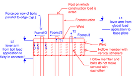
I've made another sketch to clarify the loading situation a bit. The C and T couple acting on the bolts/base plate comes from Fconstruction * L1. The base plate is welded to the hollow member, but the hollow member is not in contact with the bolts. Fconstruction is a one-time load with a known direction (not reversible).

My thought is that since I can show that Fconst/15 (the force on a single bolt with equal distribution) * L2 creates a significantly larger deflection in the bolt then the annular gap at each of the holes, this proves that the base plate will be forced into contact with all of the bolts, and the bolts can then be said to have no hole clearance and act as a group to resist shear edge breakout. This is idea is backed up by the snippet of fib 58 I included in Option 2 in my previous post. Do you see an issue with it?

1733304665390.png

1733304224333.png
 
Last edited:
You mean along the entire length of the anchor, i.e. into the page? The codes don't provide guidance but I would say along the full length of the anchor, no, but near the surface, arguably yes. The question with this kind of thing is always what is the bearing length directly below the anchor, and how deep does this propagate into the concrete member. If you look at design guides for dowels for example you'll find that they reference a bearing length of 8d (which I still can't find where it comes from) - would that mean that reinforcement placed within 8d of the surface is effective - probably, but who knows. The anchor will concentrate the bearing close to the surface of the concrete. I think if you have layers of reinforcement close to the surface say bundled hairpins or hairpins with some minimal spacing that would be ok, but I wouldn't be relying on reo along the full length of the anchor, its just too risky. Also the magnification of tension in your reo due to lever arm increases.
Yes, that is what I meant. All of what you mentioned here is in line with what I was thinking too.
The filling washers are a good way of filling the holes to get equal shear distribution - HILTI also manufacture them in up to M24 size. This would be much better than relying on the anchor displacement being less than hole clearance.

Of course if you do it as conventional cast in plate with welded shear studs or rebar then all fixings will be engaged under shear.
Agreed, these are all better ideas if starting a design from scratch. However, I'm stuck with the existing geometry on a project that was well underway by the time I joined, and making any changes at this point is the last resort (basically all I can really touch from the preliminary assumptions without creating big headaches is the supplementary reinforcement arrangement).
 
BridgeEngineer ,

Your approach seems reasonable but in this case , i am afraid other failure modes ( reduction at tensile resistance due to shear and bending, bearing failure of conc.. etc) may govern. The excerpt is copy and paste from Beton Kalender ,Precast Concrete Structures, (by Hubert Bachmann)
. the reference book for small and large end distances ; Untersuchungen über in Beton eingelassene Scherbolzen aus Betonstahl (Paschen, H. and Schönhoff, T.) And ,Pls look page 71 of the following doc.
Good Luck

1733309485526.png
 

Attachments

  • 07-GB_Column_Bases (1).pdf
    628.9 KB · Views: 5
Last edited:
That's a great reference you attached, could I ask what book it is from?

Yes, it is tensile-shear interaction that's governing the bolt group. Shear failure of the steel bolts and bearing failure of concrete are both checked but found to have very low utilizations due to high material yield strengths for both.
 

Part and Inventory Search

Sponsor