Continue to Site

Eng-Tips is the largest engineering community on the Internet

Intelligent Work Forums for Engineering Professionals

  • Congratulations SSS148 on being selected by the Eng-Tips community for having the most helpful posts in the forums last week. Way to Go!

Concrete-filled steel pipe piles (Non-composite): query 1

Status
Not open for further replies.

AK4S

Structural
Jan 2, 2015
98
I am working on the Structural Design of a Concrete-filled steel pipe pile (Non-composite)and was looking for some clarifications.
Sorry about the long post. I couldnt find a reference which goes through the analysis and so wanted to list it here to confirm my understanding.

SDC-A seismic design category. Non-seismic Load combination controls.

1.The calcs from the Geotech provided the analysis results of lateral response of the pile due to loads at the Top of the Pile.
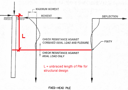
Fixed-Head condition considered at the Top.
Relevant Outputs: Max. Moment and Location of Pile Fixity from the deflection curve.(used as unbraced length for structural analysis)
Untitled_lai3yh.png


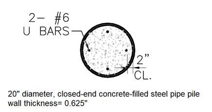
Initial Pile cross-section recommended by Geotech:
Untitled2_tkybzs.png

2. The concrete does little for Flexure as it is unreinforced (minimal rebar) and trying to get composite action to the pipe interior isn’t reliable due to the smooth inner wall of the pipe. Hence a non-composite condition is assumed for analysis.
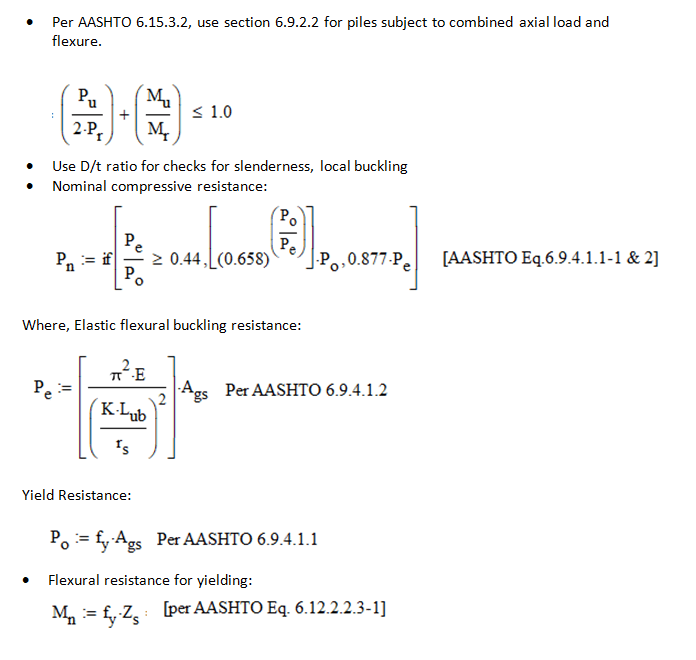
3.Went through the below steps for design:
Untitled3_kz6cad.png


Query:
[ol A]
[li]Am I missing anything in the steps above? How should I factor in the concrete to help with Axial/compressive load? Currently I have assumed only the area of the Steel Pipe Section for design (Ags). My interpretation that since the section is non-composite, I should conservatively only consider the strength of the steel pipe and not the concrete since they will compress differently under load.[/li]
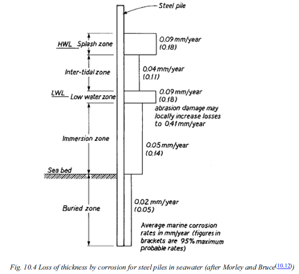
[li]Is there a guideline regarding reduction in the thickness of the steel pipe to be considered in design to account for potential corrosion in future? A coal-tar epoxy coating is already proposed for few feet at the top of the pile as a protective measure. The pile is installed in marine environment.[/li]
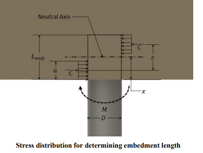
[li]How do I design/check the pile embedment into the Pile cap? Geotech recommendation was 2ft embedment to achieve fixed head conditions. Pile cap is 4ft thick. I found a reference which went through the analysis by calculating the compression resultant from the stress block for the Moment and checking this compressive stress against design strength(bearing on concrete). See below sketch. Does this look reasonable?[/li]
[/ol]
Untitled4_f9smcp.png


D.For a non-composite section, is there a guideline for the reinf. required in concrete. 1% min.?

E. Is there special rebar arrangement required around the Pile embedment? I have designed the pile cap for the required flexural reinf. and shear stirrups.
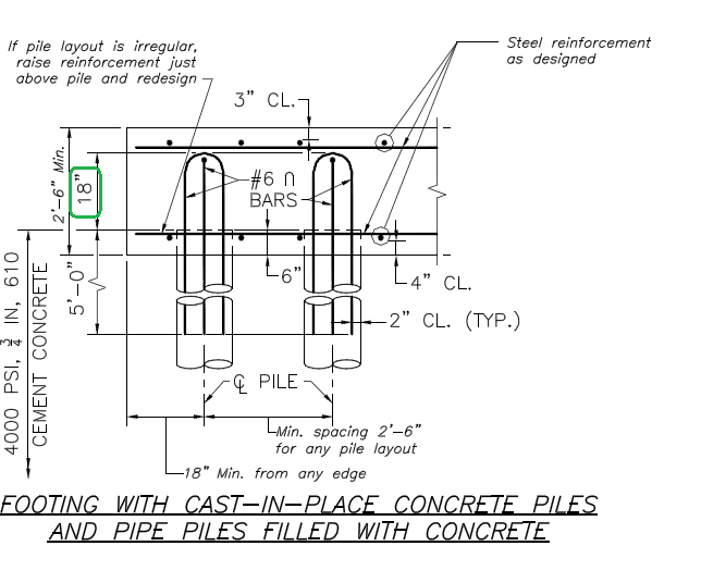
Are Additional circular stirrups around pile section, if so what is the design basis?Per below detail from State Bridge manual, the rebar from pile should project 18" into the pile cap.
Untitled5_lqd3vj.png
 
Replies continue below

Recommended for you


A = If the pile driven with closed end cap and then concrete filled, the pile is concrete filled Tube. You may look to AASHTO Concrete-Filled Tubes for the provisions. In case of WSD, The design stress for concrete could be assumed one-third of the minimum concrete strength and for steel , 40% of the minimum yield strength of steel.

B= There are guidelines for corrosion estimation. If a concrete-filled pipe pile is corroded, load-carrying capacity of the pile will remain intact. Coal-tar epoxy coating for several feet at the top of the pile as a protective measure will be helpful.


C= The sketch shows that the pile cap thk is 2'-6''. 2 ft embedment is O.K incase of 2'-6'' pile cap. I will advise to use at least 1.0 % of steel for dowel area and perform strut and tie analysis.

D= No !!!. Not necessary.. You will need 1% min. only at cap connection .

E= Additional circular stirrups around pile section and horizontal rebars at pile cap elevation will be useful to avoid bursting.

P.S. The spacing of piles shown 2' - 6''. If the dia of pile 20'', the spaing should be 60'' ..remember 3XD.
 
@HTURKAK: Thank you for your response.
A)I found that the Composite Concrete-filled Steel Tubes (CFSTs) provisions listed in AASHTO (2017,section 6.9.6) are valid for cases with or without internal rebar. For the applied loads, my pile section is adequate without the need for additional internal rebar.

1) Is there something like a non-composite concrete-filled steel tube? I was under the impression that composite action is not reliable between the smooth interior surface of the steel pipe and unreinforced concrete. Unless additional measures are taken to ensure composite action.
The limitations mentioned under CFST primarily relate to using circular tubes only, min. wall thickness of pipe and min. concrete strength.
Are there any additional measures I need to consider in my Pile detail to ensure the composite action assumed in design?

2) Per the CFST analysis my pile does not need additional internal rebar. In such a scenario, what happens at the cap connection. Is the steel pipe embedded into the Concrete Pile Cap adequate for fixity {per the analysis mentioned in my earlier post(C)}? I am also following the Standard detail from the state and extending the nominal 4#6 rebar into the cap. But this is not 1%.

B)
There are guidelines for corrosion estimation. If a concrete-filled pipe pile is corroded, load-carrying capacity of the pile will remain intact.
Can you point me to any reference where I could find the guidelines. Also since my Pile does not need internal rebar per analysis, I believe the capacity of my pile is dependent on the thickness of the Steel Pipe and so affected by corrosion. My intention was: (estimated corrosion loss thickness)+ (min. design thickness) = Thickness of steel pipe required.

Thanks for the note on the pile spacing. The sketch is an extract from the State DOT standard (does not show pile size). My piles are spaced 8ft apart.
 
AK4S,

Just my thoughts,

1) Check compressive strength use transformed section properties (Δ = PL/EA, Δstl = Δconc)
2) Design the concrete core with reinforcing steel to resist bending moment, ignore contribution from the steel casing.
3) At the bottom, develop the bars beyond the point of fixity. On top, extend the pile at least 6" into the cap, and develop the bars to comply with the "fixed head" assumption. Provide 135° hooks as required.

As for concrete filled pipe pile, There is no provision for corrosion protection as I am aware of.
 
As I remember, one of the AISC steel design manuals had a table of capacities for concrete filled pipe pile.

Mike McCann, PE, SE (WA, HI)


AK4S (Structural)(OP) said:
1) Is there something like a non-composite concrete-filled steel tube? I was under the impression that composite action is not reliable between the smooth interior surface of the steel pipe and unreinforced concrete. Unless additional measures are taken to ensure composite action.
The limitations mentioned under CFST primarily relate to using circular tubes only, min. wall thickness of pipe and min. concrete strength.
Are there any additional measures I need to consider in my Pile detail to ensure the composite action assumed in design?

2) Per the CFST analysis my pile does not need additional internal rebar. In such a scenario, what happens at the cap connection. Is the steel pipe embedded into the Concrete Pile Cap adequate for fixity {per the analysis mentioned in my earlier post(C)}? I am also following the Standard detail from the state and extending the nominal 4#6 rebar into the cap. But this is not 1%.

Pls find below my suggestions ;

1) In your case, the pile can be assumed composite for axial loading but not for bending !.. You said ' SDC-A seismic design category. Non-seismic Load combination controls' . That is, ductility is not a must and should be provided by steel pipe only . Conservatively, you may calculate the axial load resistance of pile assuming RC column and for bending resistance, you may ignore the contribution of concrete portion.

2) Steel portion embedment could be 4-6 in. In order to provide fixed head condition, the pile- cap joint shall be designed for that purpose. You have two options: either provide reinforcement cage having total length around 10 ft, (4 ft embedded in the cap and remaining in the pile core or, provide welded anchor rods with bending capacity equivalent to pipe bending capacity.( the anchor rods will be welded to steel pile interior )

Regarding CA , the following is a snap from PILE DESIGN and CONSTRUCTION PRACTICE (Tomlinson). In your case, the uppermost several
feet bitumen coated. CA can be assumed 0.02 mm /year and for 100 years service life, 2 mm CA is acceptable. IE, you are expected to perform calculations for corroded wall thk. that is, 13.88 mm (15.88-2.0) .


CA_PILE_DESIGN_and_CONSTRUCTION_PRACTICE_TOMLINSON_zp1fvo.png
 
@HTURKAK:
Thank you for the suggestions and the reference to a guideline I could use for the CA estimation.
1) The Pile size was recommended by the Geotech. For structural design, I checked and these are ok using the conservative approach.(i.e. using only the steel pipe for bending).
2)To confirm my understanding of the approach:
[ul]
[li]For bending in the pile at a point below the pile cap: use only steel pipe for capacity. (conservatively design for max. bending moment at top)[/li]
[li]The steel pipe is non-contact "spliced" with the rebar cage in the 6ft zone.[/li]
[li]For bending in the pile at the pile cap interface: Design rebar cage in RC column for capacity. Extend the rebar 4ft into the pile cap to develop it.[/li]
[/ul]


AK4S (Structural) said:
For bending in the pile at a point below the pile cap: use only steel pipe for capacity. (conservatively design for max. bending moment at top)
The steel pipe is non-contact "spliced" with the rebar cage in the 6ft zone.
For bending in the pile at the pile cap interface: Design rebar cage in RC column for capacity. Extend the rebar 4ft into the pile cap to develop it.

The approach is O.K. If you draw a sketch and post it, the subject will be more clear. Regarding the rebar cage steel area calculation , you may consider conservatively bending capacity of the steel pipe but in this case you should provide around 20000 mm2 steel...that is, 25 no 10 bar ..
 
Status
Not open for further replies.

Part and Inventory Search

Sponsor