Eng-Tips is the largest engineering community on the Internet

Intelligent Work Forums for Engineering Professionals

Concrete form deck too short 3

Status
Not open for further replies.

RattlinBog

Structural
May 27, 2022
152
0
16
US
I feel a bit ridiculous asking this, but I could use a sanity check.

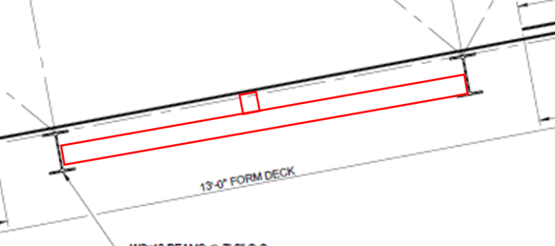
Has anyone dealt with a situation where concrete form deck (non-composite) was ordered too short and one of the ends won't be able to bear on a support? Beams are 7 ft OC, but 13 ft form deck was ordered. I can provide a sketch in the morning when I'm back at my desk.

Would it ever be acceptable to arrange the form deck in a way that the end of one deck laps the end of the next deck between supports (in mid-air)? The lap joint would need to be connected together. I've crunched some deck bending stress numbers already but wanted to see if anyone has even come across something like this before... (P.S. Slab is designed to be self-supporting. Form deck is for construction only. Area is constantly wet, so I expect the decking to rot away over time.)
 
Replies continue below

Recommended for you

SRE - if it's a question of deflection of the forms, though, wouldn't additional support points make the forms acceptable?

Though, I do see where RB says it's 20ft in the air. Might be tough to put your hands on adequate shoring posts for that sort of an application so quickly.
 
phamENG - Yes, more supports could help convert "single span with cantilever" deck to multi-span.
Vulcraft shows three-span continuous with allowable load of 113 psf and max deflection load of 71 psf. Still a problem but much better. Before electronic calculators, three-span continuous was often considered as good a performance from a given beam as routinely practical.

As you noted, time is the issue plus adding supports in an industrial setting could be tricky or not even possible.

 
Shoring likely isn't feasible (nothing is impossible but trying to be realistic). Underside of gallery is insulated and sheathed. Form deck and beams are concealed.

L4x4x3/8 angle at the laps was field welded to WT8x13 truss bottom chords and is tight to form deck. It's still not exactly ideal.

For the mid-air lap splice deck screw connections--understood about calculating available shear strength. I'm wondering about what are the actual demands that those screws would see. Sorry, my brain is fried right now after a lot of late nights. This isn't exactly a "moment" connection. Or can I assume it is and design for C=T= M/d?

 
Deflections calcs attached. Also modeled L4x4x3/8 angles taking load with the W8x18 beams in Risa-3D. I just don't have time to go through the single-angle flexural checks in AISC by hand right now... Given 75 psf DL + 20 psf LL, the L4x4x3/8 angle is at 1.7 utilization and L/y = 89 (1.4" max deflection). Assumed angle has a tributary width of about 3.5 ft and an unbraced length of 10.5 ft (obviously not great). I could have them puddle weld deck to angle from above to reduce unbraced length.

Trying to think through this. Concrete is poured and crew walks on deck to apply DL and LL. Like SRE said, this is not a pretty, uniform loading that's easily modeled with out usual formulas. Understood. The outer deck overhanging edge will engage the middle deck at the mid-air lap splice. What will happen there?

A) it deflects a large amount immediately and disaster unfolds,
B) it deflects a little and some warning is provided,
C) the deck deflects, but the deck screws at the lap engage and provide some resistance/continuity, but deflection is still there of course
D) the L4x4x3/8 angle engages in combination with the deck screws and provides some stiffness / flexural strength at the lap; still some deflection...but could the combination of the deck screws 6" OC + angle be enough to limit deflection to a reasonable amount?
 
 https://files.engineering.com/getfile.aspx?folder=7f20c5cb-7892-4ae3-bf9a-acec9462f2ff&file=form_deck_deflection.pdf
I'll stop double/triple posting after this. The last deflection calc attachment was for 20 gage deck. Assuming the contractor is right and 18 gage is what actually showed up on site, I've attached deflection calcs for 18 gage deck here. They look better. These assume the form deck is just free to deflect without any resistance from deck screws or other supports.
 
 https://files.engineering.com/getfile.aspx?folder=bc4fd8e4-86a6-48ee-a3d4-789dc675a0a5&file=form_deck_deflection_18_gage.pdf
This might have been mentioned, so sorry if I am beating a dead horse.. I see you are putting calculations in with a cantilever/overhang; the deck will see a substantially higher downward reaction with a cantilevered end than is normally anticipated. Have you considered web crippling of the deck over the first support, with all of the concrete weight on the deck plus workers stepping over the deck webs?
 
This is what I was hoping would be possible for deck shoring.

KootK said:
You could also construct some temporary wood thing between the beams to support the floating lap joints.

It's a trip to Lowes and a few thousand $$$ but taking your spans down from 7' to 3.5' would do rather a lot for deflection. That seems like a reasonable cost if it buys safety for your guys and peace of mind for you.

This stuff would still have to be erected safely but that can probably be dealt with somehow with appropriate harnessing or whatever.

C01_ik7wpx.png
 
WesternJeb, good point. Add that to the list of things that didn't occur to me in the rush.

KootK, sorry, I must've misunderstood what you meant the first time you wrote that. Seems obvious now looking at the sketch. I was thinking of some timber beam spanning from truss bottom chord to chord (not connecting to the W8 beams perpendicular to the trusses). We have those steel L4x4 angles spanning from chord to chord below the laps. I believe they'll add some stiffness at the lap but unclear how much.

Trusses are 10.5 ft apart (I accidently wrote 11.5 ft wide gallery above...that was a mistake.)
 
You have the deflections now.
I assume you will require top of slab to have specified elevations and slope.
Concrete is placed to meet this requirement for top-of-concrete, but the deck starts deflecting, increasing slab thickness without your knowledge.
Use the calculated deflections to determine increased slab thickness, see how much the concrete load (75 psf) goes up and what effect this has on the forms.

A major problem with large deflection is the physics behind the math that defines traditional beam bending equations. For this math to be reasonably correct, deflection must be "small". As deflection exceeds L/240, or so, the math results become increasing inaccurate.
This is a likely reason why Vulcraft, and others, provide the load that causes L/240 deflection.
When the L/240 load is exceeded, the deck begins performing more like a draped cable supporting gravity load than a beam. Deck is tending to support load by being in tension rather than bending. After screeding has started, probe through the still fresh concrete to get an estimate on slab thickness. If this thickness gets "too high" (engineering judgement call) terminate the pour before concrete load on deck gets out of hand.

For the overlapped decking, I would assume that as a UDL, the 3' cantilever supports about half the load that is applied to the 6' cantilever. I'll see if I an make a sketch of this.
EDIT: I believe this is more or less the result of what WesternJeb mentioned.

EDIT: Go with KootK's proposal if you can get suitable material in time. Run the numbers, space is limited, deflection and bending stress of new members will be great.

Hopefully I'm too pessimistic; deflected structural members have an uncanny way of "working together" in ways that cannot be predicted to prevent collapse. Trouble is, the "numbers" tell me this project is close to the edge of what will be successful.

After this is over, I'll give you my "guess" as to why the iron worker's situation turned out ok.

 
SRE, believe me when I say that I am absolutely nervous but trying not to let it show. I've visited the contractor/crew 2-3 times a day this week, and I've made it very clear that I don't like this mid-air splice. I bring it up every time I see them, so they all know how I feel about it. We've talked safety. One thing occurred to me is that we could have them tie off to the gallery structure above during the pour. I don't like that I'm having to use this as a crutch.

Top of slab elevation isn't very critical. It's about 9 CY total. We'll pay attention to the actual thickness. We're not putting in more volume than that one truck will bring.

I actually brought this up (minus all the engineering details) to my general manager. He fully supports me in shutting things down at the first sign of trouble. Believe it or not, we don't take safety lightly here. I've been very candid with everyone involved so we're on the same page. Even if the pour proceeds as is with the lap splice with deck screws and L4x4 angle, I believe there are steps we can take to minimize risk. Using fall protection and being very careful with load placement come to mind.

Still trying to figure our if the 6" OC deck screws at the mid-air lap are doing anything and how to go about putting a value to that. Would I just check shear demand per ft?
 
Determine the shear by assuming and calculating tension from caternary action, as KootK stated and I described.

Try to get a good night's rest. It's most important that you be "fresh" tomorrow to address the issues that come up during the pour that we have not thought of.

 
9 yd[sup]3[/sup], good, now you have another way to monitor progress. Theoretical volume of 8.2 yd[sup]3[/sup] (10.5' x 42' x 0.5'). Estimate how much concrete volume is coming out of the truck as work proceeds. Won't be accurate, just another method to back up a real-time "engineering judgement" decision. For example, if you are running out of concrete but have only placed, say, 80% of the elevated slab, time to evaluate what to do now.

 
I must not be looking at the catenary action tension quite right. Attached.

Cable tension approaches infinity as cable sag approaches 0, right? If I treat this form deck as a cable subjected to a uniformly distributed load, that means it will see a larger tension force with a smaller deflection (sag).

In my attached calcs, 90 plf (per ft of width) on a 7 ft span with 0.5" deflection yields 13.2 kip/ft. For 1" deflection --> T = 6.6 kip/ft; 0.25" deflection --> T = 26.5 kip/ft. For the 0.5" sag, I would need screws every 0.3 inches...

For fun, I checked the tensile strength of 20 gage form deck. It has an area of 0.758 in^2 per foot. (Fy*Ag)/1.67 = 22.7 kip/ft allowable tensile strength. Using the sagging cable analogy, the form deck would rip apart at 0.2" of deflection.

Obviously I'm too sleep deprived and not looking at this right. Did you mean to have me go about this a different way?

 
 https://files.engineering.com/getfile.aspx?folder=66da4acd-160e-4142-ba0c-e9d7fc57241f&file=Form_deck_catenary_action_tension.pdf
Your work is done. Try to put the project out of your mind and get some rest. In the morning, talk to the construction superintendent, turn the pour over to him, and stay out of tomorrow's operations. The best use of your engineering skills is to stand at a safe location where you can see the underside of the forms as concrete is placed. If "something" unexpected is going to happen you will be the first to see it and also best qualified to decide what, if anything, to do about. (A fringe benefit, by being away from the actual concrete placement, the superintendent will know you are serious about putting him in charge of the pour.)

Good Luck, let us know how it goes as soon a you can.

 
You're right--I needed that. Time to go home to my wife and kids.

If I learned anything, it's that I'm never going to let this happen again, at least not willfully. I never dreamed that a contractor would order deck that's too short for the project. It's too bad I learned that after the old floor slab was completely demolished by mid-day Tuesday. I'm in Minnesota, so we're going to get snow before we know it. I didn't want to leave the gallery with no floor. We'll watch it closely tomorrow.

Thank you for the help, everyone. I'll provide an update
 
Status
Not open for further replies.
Back
Top