Continue to Site

Eng-Tips is the largest engineering community on the Internet

Intelligent Work Forums for Engineering Professionals

  • Congratulations SDETERS on being selected by the Eng-Tips community for having the most helpful posts in the forums last week. Way to Go!

Concrete frame: cantilever columns or shear walls/piers

Status
Not open for further replies.

StrEng007

Structural
Aug 22, 2014
543
Realizing this is a rather vague question, I need to refresh myself on concrete frame design vs shell/wall design.

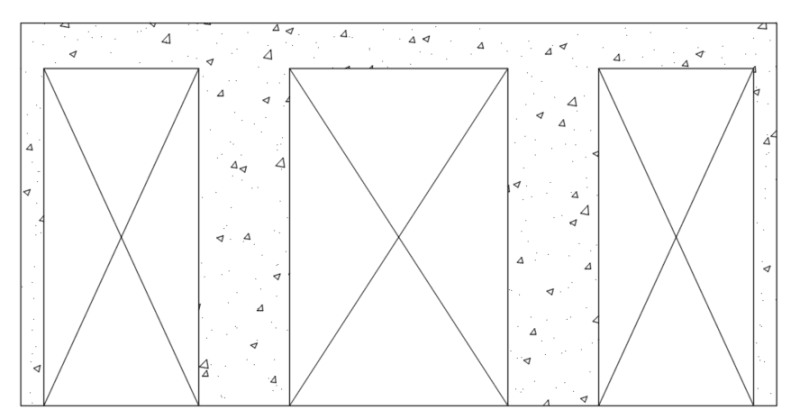
When designing a frame such as the one shown below, how does one determine if the frame MUST be designed as a concrete moment frame, or simply a gravity beam supported on individual piers that can behave like individual shear walls? I know this is going to depend on two things: the aspect ratios of the vertical elements, and the detailing of reinforcing bars.
Screenshot_2024-06-26_085729_laonpw.png
 
Replies continue below

Recommended for you

I guess my answer here would be, it's a moment frame if the shear walls can't meet the required aspect ratios within the code? This looks a lot like an old SEAOC design example (for a masonry building?). Anybody remember that one?
 
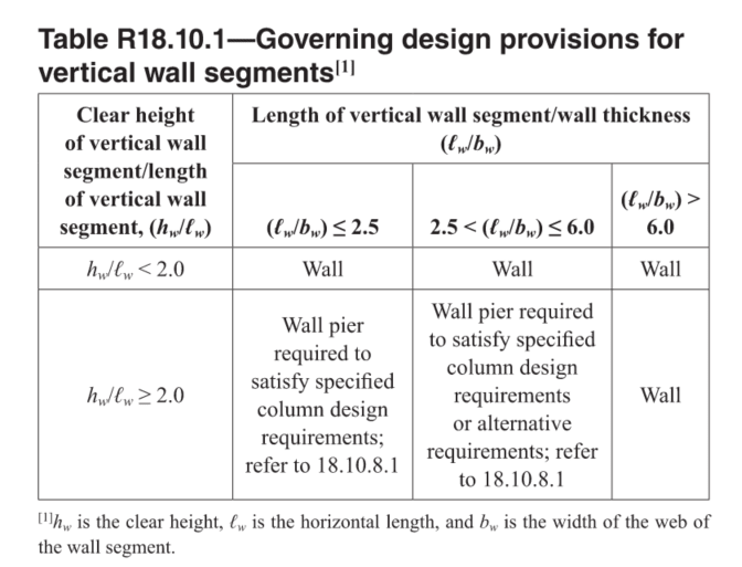
Regarding concrete walls, I referred back to ACI and found this table for Special Walls. Now my question here, would you apply this table as a general guideline for walls that are not required to be special (i.e., ordinary). The lateral load in question is purely wind driven and seismic is no where near a concern (SDC A).

Seems like all the limitation of this table refer the designer to an alternate provision for something design as a 'Special Wall'. Once a wall segment ratio classifies as a wall pier, it must satisfy the special moment frame requirements for column.

Screenshot_2024-06-27_102535_lhkxis.png
 
I'm not that familiar with ACI, but the table that you provided looks to me like the one making a distinction between slender and squat walls, i.e. how you need to design the pier itself. It has little to do with the frame vs cantilever action and more to do with shear force - bending moment interaction.

Regarding your first post, if it looks like the picture that you posted I'd say it's fine to design it as four vertical cantilevers and three beams (middle one is fixed at both ends and two outer beams are hinged at the outer ends and fixed in the middle).
I've seen some older colleagues of mine always check first if cantilevers work and then look for frame action only if necessary (and reasonable).
 
hardbutmild said:
Regarding your first post, if it looks like the picture that you posted I'd say it's fine to design it as four vertical cantilevers and three beams (middle one is fixed at both ends and two outer beams are hinged at the outer ends and fixed in the middle).
I've seen some older colleagues of mine always check first if cantilevers work and then look for frame action only if necessary (and reasonable).

After all this time, I still get tripped up about this stuff. Mostly with the detailing and how the structure will respond.

You mention leaving the outer beams hinged at the outer ends. Most of my detailing will provide the same column to beam reinforcing, whether or not I make this assumption. Often times, I call it a pin even though it may behave as fixed. And when I assume it's going to act as a frame, I don't do very much to change the detailing. (This is why steel is so much more straight forward).

This topic doesn't seem to be covered in many texts, because they all create this ideal model. In reality, is it 3 cantilevers, 2 cantilevers and a shear wall, 1 shear wall with two columns propping the ends of the beams... I'm never quite sure?

When checking 3-cantilevers, they are figuring fixed bases? But if using frame action, do they still assume the same fixed base, or something between a pin and fixed condition?
 
I always assume a fixed base in RC, but I know that some people do pinned in some cases (I believe when they do walls out of plane and detail them only with one layer of bars near the middle of the element - I always place two layers of bars, near each face). I do sometimes expect some small level of rotation, but bending moment at the bottom is always based on a fixed condition (for me).

It's not only about the detailing I believe. To me your wall looks like it has two piers in the middle and two very small vertical strips at the edges. They are so small that I doubt they could restrain the beam significantly from rotating. I also do not believe that they are long enough to ensure proper anchorage of reiforcement (to ensure a full moment capacity of the beam). In addition I do not believe that modeling it as fixed at the end you would get a significant reduction of a span bending moment. That is why I would consider it to be pinned.

It is like this for me, but I would like to hear what others have to say - in reality for a small load everything in RC is fixed. Once you increase the load it starts to deform more and more. At one point some cracks form and reinforcement starts to work. If you place a small amount of reinforcement (but larger than minimum) in the tension area at a small load section will start yielding. If it has significant ductility it will rotate just like a real pinned support, but transmitting a small moment. From that moment (of course this works only if the initial system is statically indeterminate) on the structure basically has a hinge at that section. If the moment that causes this is small - it does not influence the rest of the structure that much.

This means that assuming pinned at the end I'm saying - all is fixed, but I will place a small amunt of reinforcement at the top right and left end of the beam so that it will yield at a small load. Since I'm concerned with failure I can assume that for a failure load this transmits no moment (this will transfer it to the span) and rotates freely.

I hope that this helped with my process of dealing with this. If I made a mistake, please correct me.

 
Status
Not open for further replies.

Part and Inventory Search

Sponsor