-
1
- #1
My question involves the analysis and design of concrete moment frames used to support both gravity and lateral wind loads. Although there are many posts about utilizing the moment magnifier procedure, I can't find as many resources on the approach for second-order analysis utilizing computer methods.
Excuse the long message... Hopefully I can incite some feedback from KootK, JAE, phamENG (or any other opinion, you're all valued here!).
To get us started, I'd like to briefly outline (3) procedures for how ACI 318-11 treats slenderness effects:
(Taken from Design of Reinforced Concrete, 9th Edition, McCormac/Brown)
1. Nonlinear second-order analysis (ACI 10.10.3).
Although ACI provides a nice statement about this procedure, I don't fully grasp what it means. I feel as though the statement in 10.10.3 is not very clear or beneficial for the person who actually practices. I understand this to be a computer model that captures 2nd order effects and must "predict ultimate loads within 15 percent of those reported in tests of indeterminate reinforced structures." I don't find this very helpful (I could start an entire blog about our material Codes and the need to simplify them for the practicing engineer).
How many of you are utilizing this approach?
2. Elastic second-order analysis (ACI 10.10.4).
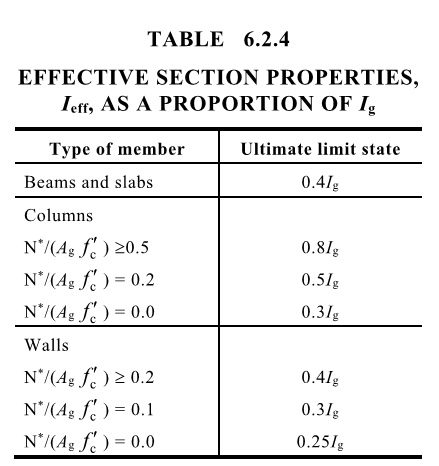
I understand this to be an approach that utilizes reduced section properties to capture the load distribution and second-order effects of members prior to failure. Since concrete is assumed to crack, we must take into account the reduction in the inertias of our members. This is the procedure I'd like to discuss in further detail.
Is it safe to assume that the majority of us are taking this approach? With tighter schedules, increasing demand on the structural engineer, and a relative compensation that hasn't shifted much from the 1980's, I find this approach to the be quickest non-academic exercise. Thoughts?
3. Moment magnification procedure (ACI 10.10.5).
This method is no stranger to this blog. It has been discussed many times from various points of view.
Now that we've covered the (3) methods, let's further discuss method #2.
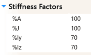
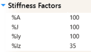
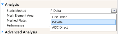
For my case, I have a concrete moment frame that is supporting both gravity loads (D, Lr, L) and lateral wind loads (W). In my computer model (IES Visual Analysis), I've set the program to perform a P-Delta analysis of the frame, and modified the stiffness of columns to utilize 70% of the strong and weak moments of inertia, Iz and Iy, respectively. Additionally, the beams in the frame utilize 35% of the strong moment of inertia, Iz. These factors are applied through Section 10.10.4.1. My understanding of how this model should be run for Strength Design:
1. Create model with columns, beams, boundary conditions, associated reinforcing, applied loads, and applicable load combinations.
2. Limit the beam and column moment of inertia per Section 10.10.4.1. Again, my option for doing this is to apply reductions via a "Stiffness Factor"
Applied to Columns
Applied to Beams
3. Run the analysis, which includes P-Delta effects. This in combination of the fact that section reductions were applied, should satisfy the Elastic second order effects required per ACI. Correct?
4. Verify that members have adequate strength (unity check) per the f'c and reinforcing provided within each member.
So far so good. Did I miss anything?
Now for my serviceability and deflection checks:
After achieving a successful strength design model of my frame, I create a separate copy so I can run my deflection checks.
1. Apply service load combinations (ie, ASD load combinations).
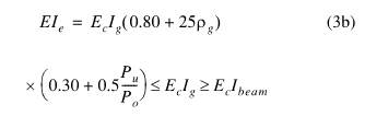
2. Per Section R10.10.4.1, in order to check service load deflections with unfactored loads, it is permissible to modify the "reduced" section properties that were applied in the strength design model. I would apply the following logic:
Columns were reduced to 0.70 Iz and 0.70 Iy
Multiplying these by 1.43, (1.43)(0.70Iz) = 1.0Iz (and the same for 1.0 Iy)
Beams were reduced to 0.35 Iz
Multiplying by 1.43, (1.43)(0.35Iz) = 0.50Iz
3. Next I re-run the analysis with the redefined section properties and investigate my deflections.
After going through ACI multiple times to review this topic, the steps above seem pretty straight forward. I would appreciate any feedback if there are some glaring mistakes in the approach I'm taking.
Excuse the long message... Hopefully I can incite some feedback from KootK, JAE, phamENG (or any other opinion, you're all valued here!).
To get us started, I'd like to briefly outline (3) procedures for how ACI 318-11 treats slenderness effects:
(Taken from Design of Reinforced Concrete, 9th Edition, McCormac/Brown)
1. Nonlinear second-order analysis (ACI 10.10.3).
Although ACI provides a nice statement about this procedure, I don't fully grasp what it means. I feel as though the statement in 10.10.3 is not very clear or beneficial for the person who actually practices. I understand this to be a computer model that captures 2nd order effects and must "predict ultimate loads within 15 percent of those reported in tests of indeterminate reinforced structures." I don't find this very helpful (I could start an entire blog about our material Codes and the need to simplify them for the practicing engineer).
How many of you are utilizing this approach?
2. Elastic second-order analysis (ACI 10.10.4).
I understand this to be an approach that utilizes reduced section properties to capture the load distribution and second-order effects of members prior to failure. Since concrete is assumed to crack, we must take into account the reduction in the inertias of our members. This is the procedure I'd like to discuss in further detail.
Is it safe to assume that the majority of us are taking this approach? With tighter schedules, increasing demand on the structural engineer, and a relative compensation that hasn't shifted much from the 1980's, I find this approach to the be quickest non-academic exercise. Thoughts?
3. Moment magnification procedure (ACI 10.10.5).
This method is no stranger to this blog. It has been discussed many times from various points of view.
Now that we've covered the (3) methods, let's further discuss method #2.
For my case, I have a concrete moment frame that is supporting both gravity loads (D, Lr, L) and lateral wind loads (W). In my computer model (IES Visual Analysis), I've set the program to perform a P-Delta analysis of the frame, and modified the stiffness of columns to utilize 70% of the strong and weak moments of inertia, Iz and Iy, respectively. Additionally, the beams in the frame utilize 35% of the strong moment of inertia, Iz. These factors are applied through Section 10.10.4.1. My understanding of how this model should be run for Strength Design:
1. Create model with columns, beams, boundary conditions, associated reinforcing, applied loads, and applicable load combinations.
2. Limit the beam and column moment of inertia per Section 10.10.4.1. Again, my option for doing this is to apply reductions via a "Stiffness Factor"
Applied to Columns
Applied to Beams
3. Run the analysis, which includes P-Delta effects. This in combination of the fact that section reductions were applied, should satisfy the Elastic second order effects required per ACI. Correct?
4. Verify that members have adequate strength (unity check) per the f'c and reinforcing provided within each member.
So far so good. Did I miss anything?
Now for my serviceability and deflection checks:
After achieving a successful strength design model of my frame, I create a separate copy so I can run my deflection checks.
1. Apply service load combinations (ie, ASD load combinations).
2. Per Section R10.10.4.1, in order to check service load deflections with unfactored loads, it is permissible to modify the "reduced" section properties that were applied in the strength design model. I would apply the following logic:
Columns were reduced to 0.70 Iz and 0.70 Iy
Multiplying these by 1.43, (1.43)(0.70Iz) = 1.0Iz (and the same for 1.0 Iy)
Beams were reduced to 0.35 Iz
Multiplying by 1.43, (1.43)(0.35Iz) = 0.50Iz
3. Next I re-run the analysis with the redefined section properties and investigate my deflections.
After going through ACI multiple times to review this topic, the steps above seem pretty straight forward. I would appreciate any feedback if there are some glaring mistakes in the approach I'm taking.