Eng-Tips is the largest engineering community on the Internet

Intelligent Work Forums for Engineering Professionals

  • Congratulations waross on being selected by the Tek-Tips community for having the most helpful posts in the forums last week. Way to Go!

Concrete Repair - Connection of Suspended Slab to Existing column

Status
Not open for further replies.

CuriousEng13

Structural
Dec 19, 2023
6
0
0
CA
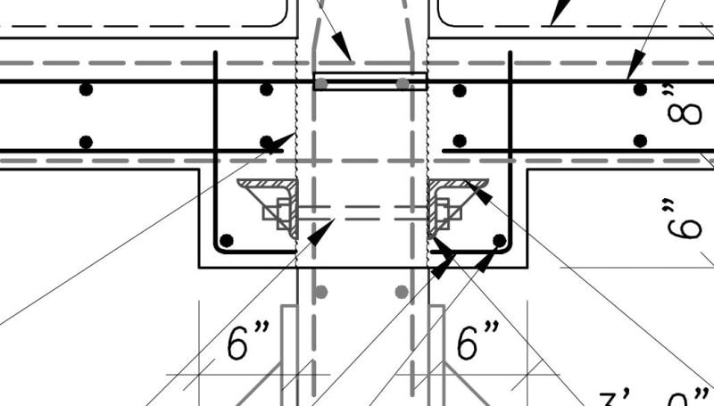
I am curious to others approach to perform concrete repair to suspended slabs around columns (multi-storey) and maintain shear integrity (punching shear issues).

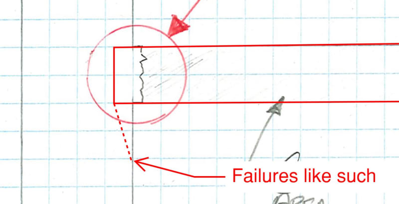
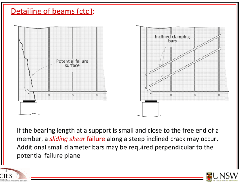
The approach in the past from our office is to remove 50mm from the column and cast the slab into that to provide a bearing condition for the slab. This doesn't sit well with me to use the column concrete cover as bearing area. I can theorize a few possible failure methods here.

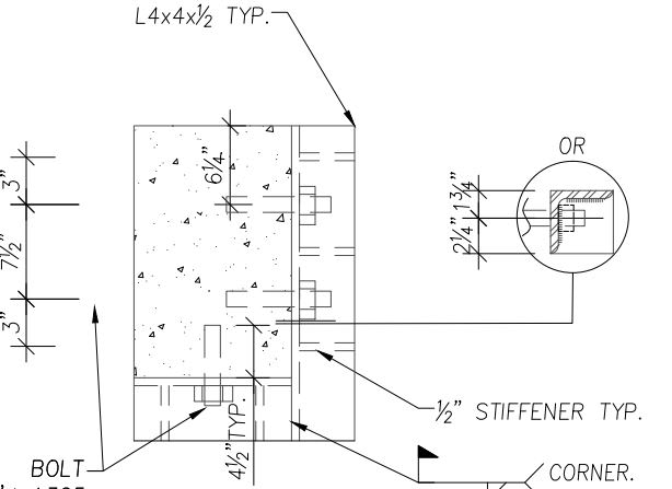
I have yet to see a solution that is realistic for concrete rehabilitation contractors to complete and be economical. I have viewed many previous repairs by others that neglected this (whether intentionally or not) and essentially rely upon shear friction, of which you cannot prove to withstand the loads. Other repairs with bolts and steel plates/angles used to create a new end bearing surface. Is adding steel structure around the column really the only solution here?

I have attached a sketch of this condition to help with clarity.
 
 https://files.engineering.com/getfile.aspx?folder=c0ad2d14-991f-40de-9288-67579354f587&file=20231219123646813.pdf
Replies continue below

Recommended for you

Looks like you understand the options. Bar far the most common are:

1. Chip off the cover (~25mm to 38mm) for a bearing seat, and add as many shear dowels as practical
2. Chip off the cover (~25mm to 38mm) for a bearing seat, and add cement grouted through-bars in the same sense as integrity steel
3. Chip off the cover (~25mm to 38mm) for a bearing seat, add angles to extend the shear face (with epoxied through-bolts), and add new bars overtop these angles

I prefer option (3). It's not really that costly and I routinely did this without issue when I was a restoration contractor. I even had a section in my intermediate slab replacement estimate sheet for this and it never amounted to anything significant. I actually found the through-bar grouting far more of a headache given the awkward size of shoehorning a bar in there and holding it in place during liquid grouting.

Below is a common detail for option (3). If you don't want to create the haunch then you can reverse the angle leg and keep it in the drop.

Capture3_sxddqp.jpg
 
This might hurt the look/architecture a bit, but the easiest way for me is to add cast-in-place concrete corbels or steel angles/plates like you mentioned.

Removing 50mm from the column might cut into the column rebar, but if you don't cut the rebar or column ties, it's not a bad idea. You're maintaining the continuity of the column and reapplying the cover. I'd use repair mortar or repair concrete instead of standard concrete just to make sure that the concrete bonds well and serves its purpose as cover and axial load transfer. You're only using 2" bearing for the slab, but it might calc out. What failure modes were you thinking?
 
Enable, Thanks for the reply, glad to see others have been through similar issues.

1)If concrete is not removed all around or it is a corner column, it is difficult to get the required development for shear dowels.
2) Not the worst, but again at a corner not possible.

1 & 2) At times the existing congestion of flexural steel at this interface becomes a problem with the contractor. Either they cannot drill or there is simply not enough space to add sufficient reinforcing. At times we are already trying to add dowels to account for corroded/loss of cross section on the flexural steel.

3) I like this approach. This is similar to what I have observed already installed from previous repairs but they have left the angle exposed and not cast in. Are you designing the shear to be completly taken by the bolts here? Also I could see issues with drilling at hitting column vertical steel and the contractor making swiss cheese of the column in an attempt to through bolt.

MilkShake,

The 50mm "key" in the column seems to work, but my understanding of the concrete cover in columns is it is not typically relied upon for strength. Additionally, I see failure methods of the wedge below the bearing seat spalling of due to shear friction failures. The bearing calcs out but im not sure a simply bearing calc really covers all of this condition.

Capture_qvzm6m.jpg
 
Someone correct me if I'm wrong, but that wedge is not a failure plane. I don't think this is a shear friction issue with the bearing seat. It's axial loading. The only reason that area would fail is if the cover spalled or there is a bearing failure. You can rely 100% on the shear friction if you design it that way, but let's say shear friction fails. It will still go into bearing.


concrete cover in columns is it is not typically relied upon for strength

I disagree. In column flexure, we consider the cover area in the compression block (in the tension-compression moment couple). We also consider it for axial load calculations. The cover itself is monolithic with the concrete column. It's not a separate failure plane interrupted by the rebar. I believe that we can consider it to be load bearing. We only don't consider it for tension, but in reinforced concrete, that's always the case.

Take the example of a 50mm concrete ledge on a singly reinforced foundation wall. Even though the reinforcement is in the middle and there is a bearing plane outside it, the ledge won't shear off as a result because it's monolithically poured with the rest of the wall.

Another example where we consider the concrete cover to be load-bearing is in Enable's example above, with anchor bolts resting on the cover. If it didn't, the bolts would be in flexure and the angle solution wouldn't work.
 
For (1) You'll probably never get dowels through the shear friction mechanism to work out, especially since we are forbidden from ratioing capacity relative to achieved depth (as far as I know). That said, that's exactly what you need to do in that scenario (or rely on dowel action rather than shear friction).

RE: no corbel. You absolutely need to fireproof the angles. The easiest way is in concrete since you're pouring that anyways. Fireproofing spray or intumescent paint will also work though.

We scan the columns for vertical bars ahead of demo (maintain a flat surface for the scanner) and so far, on 100s of garages, I've been able to drill for dowels or through-bolts every single time. Not always easy but we've always done it while maintaining the integrity of the column. When using the angles it often means shop drilling one side and site (mag) drilling the opposing side once hole inclinations are known. If your contractor says they can't get it done, it just means that they don't want to supervise the work closely enough to get the job done.

RE: corner angles. We can absolutely do this (see below). If you prefer a through-bolt approach you can use backing plates and cast them in on the other side of the column (chip off cover and bury them inside). Bolts are typically designed for all of the shear in the case of through-bolts, but that's hard to get to work with epoxy only.

Capture_1_z8aawi.jpg
 
MSL said:
Someone correct me if I'm wrong, but that wedge is not a failure plane. I don't think this is a shear friction issue with the bearing seat. It's axial loading. The only reason that area would fail is if the cover spalled or there is a bearing failure. You can rely 100% on the shear friction if you design it that way, but let's say shear friction fails. It will still go into bearing.

One thing to consider is that due to the demolition process that bearing seat is likely to have microfractures for some distance along the vertical reinforcing steel. The hammer striking the bar causing it to vibrate being the biggest concern. This is, in part, why we restrict hammer sizes for final chipping.
 
Thanks all.

In part, I'm looking to comprise a compelling case to the others in the office on the reason why the 50mm key into the column is not sufficient, if that is indeed the verdict.

There is no doubt to me that the key method is the simplest repair if it can be justified; I then question why it seems i have not seen any others complete this, its always steel or nothing from what i have seen.
 
MSL said:
Someone correct me if I'm wrong, but that wedge is not a failure plane. I don't think this is a shear friction issue with the bearing seat. It's axial loading. The only reason that area would fail is if the cover spalled or there is a bearing failure. You can rely 100% on the shear friction if you design it that way, but let's say shear friction fails. It will still go into bearing.

I think there is a potential failure mode here, as illustrated in this Gilbert slide. We also check large point loads adjacent to free edges (say when using a hydraulic jack on an abutment to lift a bridge).
Gilbert_Sliding_Shear_k9mtv4.png


Granted, the methodology to perform that check is up for debate (I'm actually in the middle of a claim over the issue). I'd love to hear how others approach it.

KootK, this may be your chance to revive the discussion here:
 
@Lomarandil I'm not entirely convinced that the sliding shear failure mode applies here (though I've never heard of it and it's good to learn something new; thanks). I'd have to read more about it, but on the surface, it seems like a non-negligible amount of beam axial load, lateral instability, or buckling of the column will cause that failure combined with the regular shear. This is also a weird little thing I thought about, but perhaps the miniscule curvature a beam experiences (like a 25mm deflection at midpoint) can impart some level of axial load, which can cause sliding for a heavily loaded beam with uneven loading. But it's a thought in my head and probably not anything real or quantifiable.

Enable made a great point that chipping that area will create microfractures, and that's a compelling argument for the wedge failure mode that CuriousEng13 pointed out.
 
Status
Not open for further replies.
Back
Top