LonelyDeer
Structural
Hello. I have a question about design of concrete shells with three-layer method described in p.7.3.2.2 fib Model Code for concrete structures.
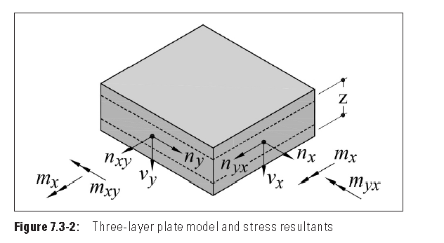
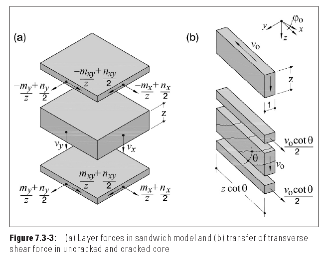
The main idea of method is that we divide shell on three layers. The outer layers provide resistance to the in-plane effects of both the bending and the in-plane axial loading, while core provides a shear transfer between the outer layers.
The action effects of applied loads are expressed as eight components, three moments per unit width(mx,my,mxy), three axial forces per unit width (nx,ny,nxy) and two shear forces per unit width ((vx,vy) in directions parallel to the orthogonal reinforcement.
(there is positive directions of forces on picture)
Then we use some formula to find forces in the outer layers.
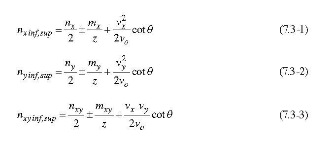
where:
The subscript notation inf and sup refer to the interior and superior faces on the element. The interior face is the tensile face for an element in positive bending.
v0=sqrt(vx2+vy2)
\theta is the inclination of compression stresses in the core layer
Here we have the picture for the equations:
And here is my question(s):
1. Why is plus sign in equations (7.3-1 - 7.3-3) in front of
/(vx)^2/(2*v0)
/ (vy)^2/(2*v0)
/ (vx*vy)/(2*v0)
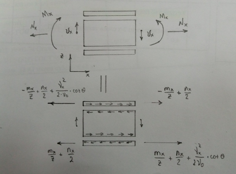
2. Why v0*cot(\theta)/2 direction in sup part of shell is the same as inf part?
3.I don't understand how we got this part in equation.
Does anybody have any information about the three-layer model? Can you explain me this part?
Do you know any articles explained this?
The main idea of method is that we divide shell on three layers. The outer layers provide resistance to the in-plane effects of both the bending and the in-plane axial loading, while core provides a shear transfer between the outer layers.
The action effects of applied loads are expressed as eight components, three moments per unit width(mx,my,mxy), three axial forces per unit width (nx,ny,nxy) and two shear forces per unit width ((vx,vy) in directions parallel to the orthogonal reinforcement.
(there is positive directions of forces on picture)
Then we use some formula to find forces in the outer layers.
where:
The subscript notation inf and sup refer to the interior and superior faces on the element. The interior face is the tensile face for an element in positive bending.
v0=sqrt(vx2+vy2)
\theta is the inclination of compression stresses in the core layer
Here we have the picture for the equations:
And here is my question(s):
1. Why is plus sign in equations (7.3-1 - 7.3-3) in front of
/(vx)^2/(2*v0)
/ (vy)^2/(2*v0)
/ (vx*vy)/(2*v0)
2. Why v0*cot(\theta)/2 direction in sup part of shell is the same as inf part?
3.I don't understand how we got this part in equation.
Does anybody have any information about the three-layer model? Can you explain me this part?
Do you know any articles explained this?