Continue to Site

Eng-Tips is the largest engineering community on the Internet

Intelligent Work Forums for Engineering Professionals

  • Congratulations cowski on being selected by the Eng-Tips community for having the most helpful posts in the forums last week. Way to Go!

Concrete slab - concrete wall connection

Status
Not open for further replies.

mats12

Geotechnical
Dec 17, 2016
181
Hello, I have a question regarding modeling a concrete slab.

If a concrete slab is laying on top of masonry walls - that is pinned connection, right?

But what about when there is a concrete wall instead of masonry? Should I select fixed connection between wall and slab or not? If there is fixed connection that means that the moment also appears in the concrete walls. What if i dont want that. Maybe it depends how i detail reinforcement between slab - wall?

There is an example beloq... im not sure how to model it properly.
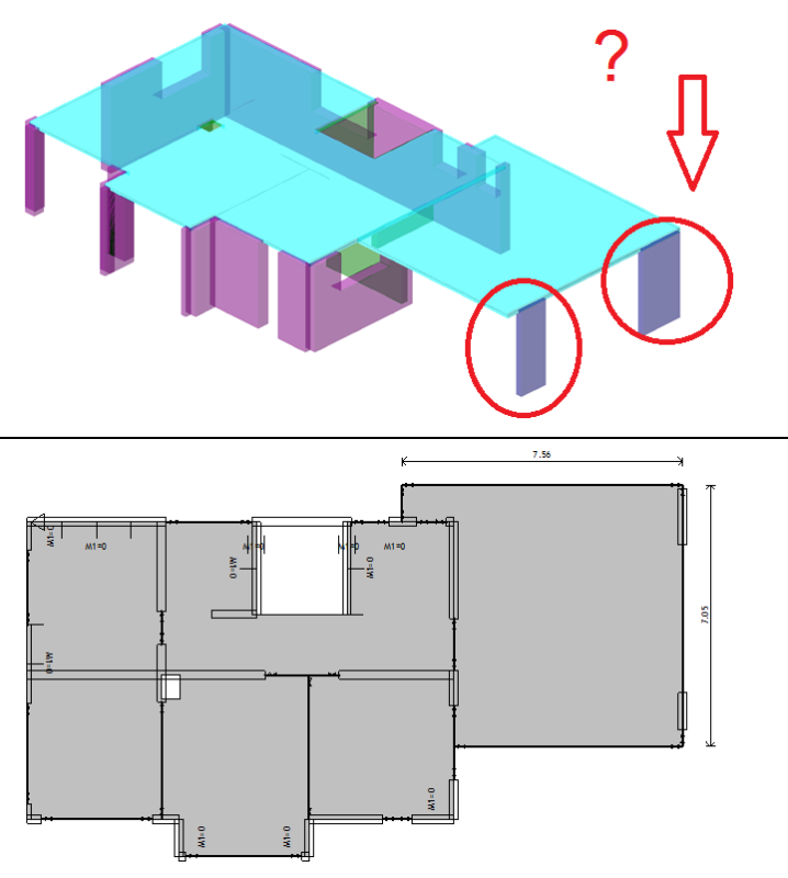
slab1_hsfkr7.png


suggestions?

tnx
 
Replies continue below

Recommended for you

Pinned. There is always a degree of fixity in these connections, depending on the detailing, but the assumption of pinned at the ends for analysis is appropriate.
 
Ok tnx for answer.

But what about concrete walls, does that mean walls are loaded only vertically - axial compression(no moments)?
 
I agree with Hokie's comment.

As a corollary though, if there is a continuous deep lintel over the top of the walls, I might consider it fixed, depending on the depth and reinforcing.

Mike McCann, PE, SE (WA)


The assumption of pinned is conservative for the slab. You should also use a conservative assumption for the walls, but this is normally just due to eccentric loading, not to fixity.
 
well in any case, there definitely are some bending moment in the concrete walls because of slab (eccentric loading as you said).
 
Yes, just as we always design columns for at least a degree of eccentric loading.
 
Maybe it depends how i detail reinforcement between slab - wall?

That is essentially it. If you are doing a FEA model, there likely isn't a release between the plate elements in the first place.

For hand calcs (for out-of-plane loads like wind) most people will still treat the wall as pinned at that point. However it will not be perfectly "pinned": some degree of fixity will be there.
 
I would just like to add, that it does depend on the purpose of the model for ultimate limit state, pin is a good choice unless you can detail the connection approprately which is very hard for think walls.

However for serviceability limit states, a fixed connection maybe more approprate and should be review accordingly. In vibration analysis the walls would genrally be fixed.

"Programming today is a race between software engineers striving to build bigger and better idiot-proof programs, and the Universe trying to produce bigger and better idiots. So far, the Universe is winning."
 
WARose has hit on a problem often broached here by people using computers. They want to know whether to use fixed or pinned, when the answer is usually "neither". A degree of fixity, but not fixed.
 
Some additional thoughts:

1) In many situations, the eccentricity of load on the walls due to intentional or inadvertent moment transfer can be substantial. To the tune of several feet really as the effective eccentricity is the distance to the inflection point in the slab. I wonder about this often when designing basement concrete walls supporting ramps. In that scenario, you have a short wall both above and below the ramp joint and, as such, there is considerable stiffness in the wall system. If one explicitly considers the amount of eccentric load that implies in the walls, the walls really don't work. Certainly not the 8" walls with one mat of reinforcing that virtually everyone in my market uses for this situation. That said, I've yet to ever see a failure of this sort.

2) While the pinned assumption is generally conservative for slab flexure, it may be unconservative for slab shear (one way or punching. One is usually forced to connect walls and slabs in ways that introduce some measure of joint fixity. Moreover, for the reasons mentioned by rowingengineer, it is often prudent to detail these joints for nominal moment transfer regardless of our modelling assumptions for the sake of crack control and general serviceability. All this means that there will be negative moment at the wall to slab joint regardless of our modelling assumptions. In my opinion, that means that shear capacity should be based on a "d" dimension measured from the bottom of the slab to the centroid of the top steel. But our pinned model indicates no demand for slab top steel. If our shear capacities were to be based on the "d" associated with the bottom steel, the effective slab depth would be something like 1.5" and our shear capacities woefully small. In practice, we usually seem to just provide some nominal top steel and hope for the best with regard to shear. And, thankfully, that seems to work out just fine.

I like to debate structural engineering theory -- a lot. If I challenge you on something, know that I'm doing so because I respect your opinion enough to either change it or adopt it.
 
Also, in reality, creep effects in the slab and walls will tend to substantially dissipate the moment in the joint. Pretty tough to quantify that effect in practice however.

I like to debate structural engineering theory -- a lot. If I challenge you on something, know that I'm doing so because I respect your opinion enough to either change it or adopt it.
 
Wait, you should analyze the slab as pinned in this situation but analyze the wall as fixed?
 
being conservative in both cases I understand YES.
 
Leftwow,
That was not my advice. Some fixity needs to be allowed for both, but neither is either fixed or pinned. For slabs, we analyze as pinned, then reinforce for nominal fixity. For walls, we use a degree of eccentricity for the vertical load, then add the out of plane loading.
 
What hokie66 said for ultimate limit state analysis.

"Programming today is a race between software engineers striving to build bigger and better idiot-proof programs, and the Universe trying to produce bigger and better idiots. So far, the Universe is winning."
 
Im from Europe so I may not be familiar with this method:

"For walls, we use a degree of eccentricity for the vertical load, then add the out of plane loading."

Can someone please explain to me or add a sketch for elaboration.

Id relly like to learn this.
 
I might be wrong but what I think hokie implies is
that you still have design the wall for a minimum moment
with that moment being caused by the eccentric loading.

It is a function of the vertical axel load, not sure if
the eurocode has that already accounted for in the columns/wall
design.
 
Status
Not open for further replies.

Part and Inventory Search

Sponsor