Eng-Tips is the largest engineering community on the Internet

Intelligent Work Forums for Engineering Professionals

Concrete Slab - Z Shape Section Detail 1

Status
Not open for further replies.

CovertShear

Structural
Nov 8, 2022
36
0
0
SK
Let me get right to it:

Problem:

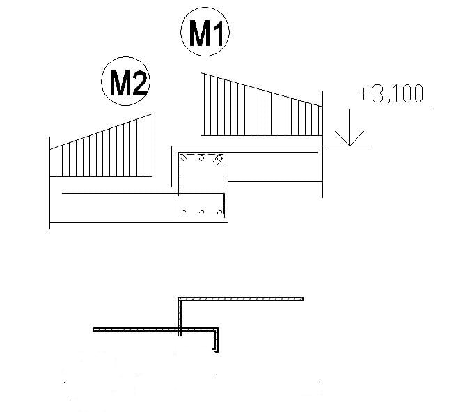
- You have a elevation jump in a monolithic concrete slab (ceiling), or a Z-shape section if you will.

- You want to detail a reinforcement for hogging bending moments M1 and M2 (perpendicular to the "jump beam").


Rebar_bend_B1_kzxgvl.jpg


1) I have done this detail before using two outward facing U-shape bends usually.

Question:

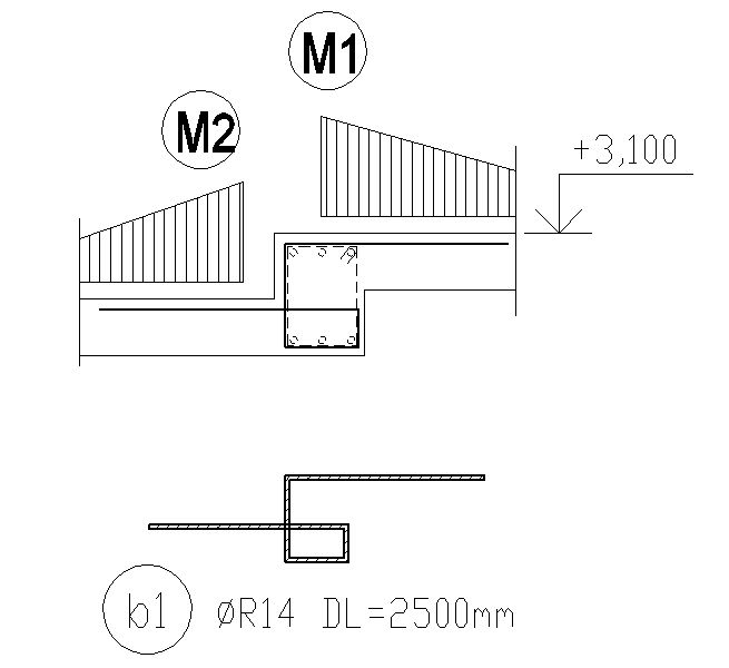
- What do you think about the rebar "b1" in the picture?

- I haven't used this yet, but it kinda makes sense to me, the rebar could have a space for development length inside the "jump beam" it seems.

- Basically I want to reinforce the hogging moments M1 and M2 with a single rebar bend, would that work?
 
Replies continue below

Recommended for you

My suggestion would be two separate hogging reinf. L shaped and closed stirrup for the rectangular beam ..

Rebar_bend_B1_kzxgvl_co0r4w.jpg


EDIT: In order to achieve full joint efficiency , the beam width should be increased or use smaller dia. reinf. rather than using U type , Z type reinf. which have constructibility problems ..


I cannot give you the formula for success, but I can give you the formula for failure..It is: Try to please everybody.
 
@EZBuilding
@BridgeSmith

- Thats a valid point, but I want to do something different than U-shape bars. I feel like their development length in this case is very small.

@HTURKAK

- I like the idea of L-shape bars. I think i will do L-shape for the upper slab, and a U-shape for the bottom one.

 
If it were a big step like this, my detailing would likely look as though it were two slabs coming into a beam. Develop my moment into the beam, the stirrups should work as hangers and then do a strut and tie check for the moment transfer after justifying that I've got development at the bend. Making that node work is going to be key. If you can't make the nodes work, you can start using something that's got faster development like a plate or a headed anchor or something.

If you can slope those vertical form lines, or make the joint wider, you might have some options to maintain bar continuity a bit better or provide an easier load path that's a bit more like lapping things together.
 
I recall coming across a thread around here looking at this situation from a strut & tie perspective...someone might be able to find it (likely where Koot would enthusiastically take this thread also)

Tomfh said:
I work on a minimum of 500mm, or twice the slab thickness, whichever is larger.

I've always wondered how different individuals settle on the numbers for this sort of rule of thumb. More senior members at my firm like 300mm as a minimum (assuming a typical RC slab around 200mm-ish thickness) but I don't get the impression anyone has ever really checked in detail what width is actually needed for full capacity.

----------------------------------------------------------------------

Why yes, I do in fact have no idea what I'm talking about
 
@TLHS

How would you do the strut and tie check for the moment transfer?
Can you link me a good source?

@Tomfh

I like that shape, good.

@Just Some Nerd

Finding that thread would be nice.
 
HTURKAK has it... you can place the bars in the beam with little effort. If the hook's too long, tilt the top bar in the lower slab.

-----*****-----
So strange to see the singularity approaching while the entire planet is rapidly turning into a hellscape. -John Coates

-Dik
 
Just Some Nerd said:
I've always wondered how different individuals settle on the numbers for this sort of rule of thumb

500mm was simply our office standard for a basic fold. And 2x D generally gets you full capacity without too much fussing around.

You can of course get higher capacity with a thinner fold if it's reinforced properly.

This thread has a good document showing test results:

 
tomfh... cranking a bar like a Z is not good. if the bar is in tension then at the bottom bend, if in tension, the resulting force component is to 'pop out' the concrete surface.

-----*****-----
So strange to see the singularity approaching while the entire planet is rapidly turning into a hellscape. -John Coates

-Dik
 
Yes it’s probably not ideal to turn the cog out that way.

It’s a fairy standard slab fold detail but it will likely suffer the same issues like you see in retaining walls where the bottom cog turns the “wrong” way.
 
The detail proposed with two 'L' bars will not achieve full joint efficiency. For that, you would need 'U' bars top and bottom, combined with stirrups of same size bars. But perhaps you don't need the joint to develop the full moment capacity. The 4 bend bar shown in the first post would do the job, but as others have said, presents a constructability issue.
 
Status
Not open for further replies.
Back
Top