Continue to Site

Eng-Tips is the largest engineering community on the Internet

Intelligent Work Forums for Engineering Professionals

  • Congratulations KootK on being selected by the Eng-Tips community for having the most helpful posts in the forums last week. Way to Go!

Concrete strength for a lifting point 2

Status
Not open for further replies.

toothless48

Mechanical
Oct 27, 2014
29
Hello, I work in a small R&D lab. Our CTO had our technician set up a lifting point using a concrete beam in the ceiling of our lab (a week when I was out). I would like to validate the strength of this setup to make sure it is safe, since it was done very ad-hoc.

The setup is a 3/4"-10 double threaded stud through an existing ~3/4" conduit sleeve in a concrete beam. The beam's dimensions are 12" in height and 12" in width. The sleeve is 8" from the bottom of the beam. The two ends of the stud are nutted + pinned, and are used to hang chain for a chainfall.

I have done a hand calculation for the stud (125 ksi min tensile strength) assuming two-point beam bending. Using a factor of safety of 5, I found it to have a 700 lb capacity (350 lb vertical load per side).

My question is: how can I validate the strength of the concrete / what should I consider for that analysis? I do not have a lot of experience with concrete analysis, so I would appreciate any insight or references. I do not have access to any of the building plans or technical information. I would also appreciate feedback if it is a bad idea to even try to do a validation for this - I am just trying to do due diligence one way or the other.

Some folks in the office already lifted 600 lb with the setup (again, I was not involved when they did). If we do decide on an actual load capacity, we will test it at 125%.

Thank you
Mike
 
Replies continue below

Recommended for you

I really don't think the beam is in any danger from a ~300kg load, but that's relatively easy to show.

The issue for me is the horrible connection "design" of the chain attachment.

There are a whole host of things going on here with forces in all sorts of directions. Can you give us a whole picture of the set up or draw it?

Inginuity drew it as hanging equally from both sides, but your description is rather vague. Do they hang straight down or connect to a single block? Do they just lift something up vertically then lower it down again?

Chains really need an end connection to properly form around the end chain link. Like the red links in this photo. And the design by StrcrPono above.

image_s51nxg.png


Remember - More details = better answers
Also: If you get a response it's polite to respond to it.
 
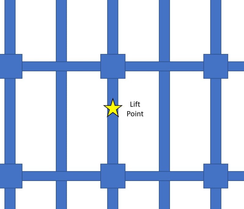
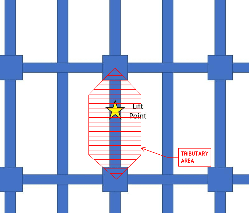
Ingenuity - thanks again for the detailed response. For "option 1", could you confirm how you calculated the 18,000 lbf dead load? I assume it is the beam weight + slab weight, using a typical concrete density. I've included a quick sketch of the beam geometry - would the tributary area be the beam span x the beam spacing, or is it decreased due to the contribution of perpendicular members taking some of the load?

To answer your previous question, the space above the beam is an occupied floor.

ppt_cad_jngwgw.jpg


LittleInch - I appreciate the feedback. The two chains connect to a single chain hoist. Due to the geometry of the beam and the size of the chains, the beam spreads the chains, so the chains hang vertically next to the beam.
 
toothless48:

For the example I gave - assumed to be what we call a one-way beam-and-slab system - it is simply the cross-sectional area of concrete (in ft[sup]2[/sup]) over the 10' assumed width x span length, so SW = [10' x 6"/12 slab + (12"/12 beam web depth) x (12"/12 beam width)] x 20' x 150 lb/ft[sup]3[/sup] = 18,000 lb.f

For your actual case with perpendicular beams the tributary area gets reduced slightly, as follows:

PLAN_vl7iul.png
 
Toothless48:
You either want to get the stud/bolt threads out of the high shear and bending regions or you have to account for a significant reduction in shear and bending cap’y. because of the threads. Your photo shows that the bolt will suffer a significant bending problem because of the broken out hole at the face of the conc. beam. That would normally be the bolt bearing region, although the conc. bearing stresses would be very high. If I were doing this, I would make two steel plates, maybe .75” thk., by 8” wide, by about 20” long (vert. direction). That is about 2” above the bolt, 8” to the bot. of the conc. beam, plus 10” below the beam. These stl. pls. would be bolted tight to the sides conc. beam, by you existing bolt. Then, at the bot. of the stl. pls. provide drilled holes for two shackles, or cut pear shaped holes for a chain hook. My stl. pl. sizes are for design concept only, you design the pls. for your loads, and check your thru bolt cap’y.
 
In my opinion a steel trapeze would be unnecessary for 700 lbs.

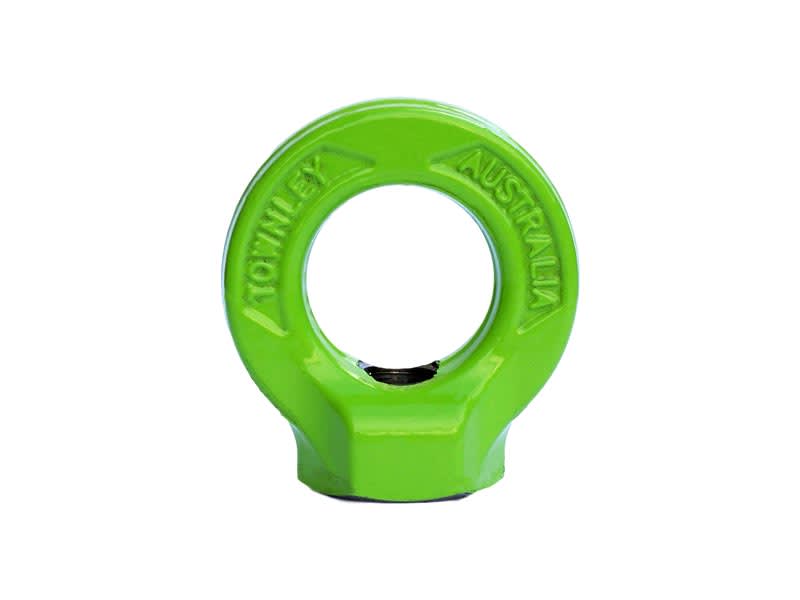
I’d grout fill the voids, then use a rated eye nut plus plate washer on each side, then connect the chains to the eyes with rated shackles.

97FB374A-69BB-4C09-976E-FCAA48FBD548_dxtuvx.jpg
 
I'm with dhengr here. If 300kg fell off on top my foot I wouldn't be calling it a small load.

I would remove your bolt, repair the ends of the hole, use a solid bar for the majority of the beam width with enough threads left to tighten onto the steel plates and then attach your chains. You may want to add a cross bar between the two plates under the bean to reduce any bending moment on the plates or axial force on the bolt.

Then paint it yellow and make it look professional. What you have there would not pass inspection by any sort of certifying body or any client would see it and think these guys are cowboys...

Remember - More details = better answers
Also: If you get a response it's polite to respond to it.
 
Status
Not open for further replies.

Part and Inventory Search

Sponsor