Continue to Site

Eng-Tips is the largest engineering community on the Internet

Intelligent Work Forums for Engineering Professionals

  • Congratulations KootK on being selected by the Eng-Tips community for having the most helpful posts in the forums last week. Way to Go!

Concrete Wall Reinforcement....Vertical Reinforcement Layer

Status
Not open for further replies.

JohnRwals

Structural
Jul 8, 2020
146
Hello!

I have a question about wall reinforcement layout.
Wall design detail shows horizontal reinforcement close to the exterior face like Wall 2.
What happens if I put vertical rebars close to the face like Wall 1?
Does ACI refer to this problem specifically?
Eurocode seems to mention this detail:
they prefer Wall 2 to prevent potential buckling of vertical rebars and surface crack.
In case of Wall 1 layout, they recommend extra tie bars (transverse reinforcement)
between vertical reinforcement layers.

Is there any test or paper to compare the difference between two layouts?
(Let's assume both models have the same d value.)
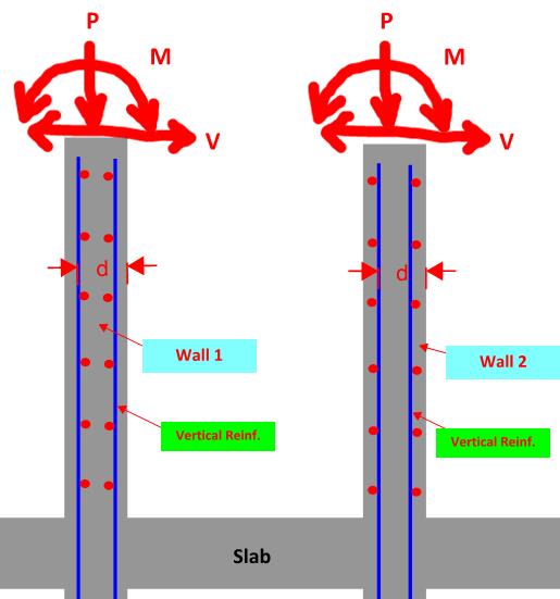
Wall_Reinf-1_a7ack6.jpg


Thanks!

JRW
 
Replies continue below

Recommended for you

Where I practice, wall 1 is common as the walls are vertically spanning and we neglect the contribution of the compression side reinforcing when determining capacity. Where we need compression reinforcement, that reinforcement needs to be tied appropriately.

Often, the neutral axis depth is so shallow that those bars are in tension anyway when there's any bending.

Now, if a wall was purely a compression element with only incidental bending, then I'd agree that wall 2 layout makes more sense.
 
For the moment shown (wall spanning or cantilevering primarily vertically), and "d" being the same (which is not typically the case), the capacities are the same, so the only real difference that I see is that Wall 2 would be a little easier to construct.

However, if the "d" for the vertical steel is the same for both, then either it was designed with a lower bending capacity than it could have had, or Wall 2 is likely violating the required concrete cover to the horizontal bars.

Rod Smith, P.E., The artist formerly known as HotRod10
 
Verticals in the outer layer are best for flexural tension capacity when spanning vertically, like in a retaining wall or other wall with significant lateral pressure. Placing horizontals in the outer layer is best for consolidation of the concrete, as it allows more space for placement and compaction. In walls which are purely compressive, construction is facilitated by standing verticals first, tying horizontals as you go. Repeat for other side, so you get vertical in outer layer one side, inner layer other side. That would be 'wall 3'.
 
Wall 1 is most common in my local. Wall 2 has the easier rebar installation if they are not pre-assembled rebar mats.
Neither is prohibited in ACI as long as the calcs work and you provide adequate cover.
In general, I'd say Wall 1 has higher flexural resistance and Wall 2 may be used for walls where axial loads control the design.
 
I was surprised to see some people adopt Wall 1.

In my opinion, both models do not make huge difference
as long as strength ('d') and crack issue can be solved.
Also, I guess ACI does not say anything specifically.
But, Eurocode seems to mention in case of buckling in the wall.
(In principle, this makes sense.)
So, either wall 2 or wall 1 with transverse reinforcement (like tie bars) should be used
according to Eurocode as long as walls take compression.
This means the difference between Wall 1 and 2 may not be minor
as can be modified for concrete consolidation or rebar cage fabrication.

Should I treat this issue differently according to the seismic zone?
For SDC A/B/C?, Wall 1 & 2 can be interchangeable with minor consideration?
But, for SCD D/F, Wall 2 should be used like in structural walls?

JRW
 
You must either muck up the design completely, or have extreme loads, for buckling of wall reinforcement to ever be an issue. For the rebar to buckle, the entire wall has to buckle, and that almost never controls in design of massive structures (i.e. concrete walls) with large second moment of area or equivalently large "plate thickness".

Wall 1 will have more flexural capacity with the same wall thickness, while wall 2 will have more buckling capacity - in theory. If you actually want to calculate the effect of confinement on buckling resistance, you need rocket science software (e.g., ABAQUS or ANSYS) and a project budget reserved for things such as nuclear power plants or US DoD sponsored bunkers. In practice, the marginal increase of confinement is not worth trading for flexural resistance provided by Wall 1.

You´ll probably find that its easier to design concrete walls to resist compression than tension, so flexural design will likely govern in any case - including seismic. If you are very worried about wall rebar buckling, I would recommend you to just put some code-prescribed stirrups in the walls or run a fancy analysis.
 
JohnRwals said:
I was surprised to see some people adopt Wall 1.

I had a similar reaction, Wall 2 is the standard choice in my (admittedly limited) experience. I've only seen it done like Wall 1 when said wall is designed as a deep beam. On plan I have only ever seen it explicitly called out as a deep beam with its own detail, never have I seen one that points to the wall detail.

centondollar said:
In practice, the marginal increase of confinement is not worth trading for flexural resistance provided by Wall 1.

For corner/junction/end detailing (particularly if dealing boundary elements), it makes sense to me to just keep horizontal reinforcement on the outside everywhere. I wouldn't think it makes a significant difference either way for the middle sections of the wall, and any reduction in flexural capacity can be accounted for with some extra steel. It's also easier to deal with on-site when the vertical bars are on the inside.
 
Status
Not open for further replies.

Part and Inventory Search

Sponsor