Continue to Site

Eng-Tips is the largest engineering community on the Internet

Intelligent Work Forums for Engineering Professionals

  • Congratulations KootK on being selected by the Eng-Tips community for having the most helpful posts in the forums last week. Way to Go!

Condensing steam turbine,isoentropical efficiency.

Status
Not open for further replies.

Gabriele.P

Mechanical
Oct 6, 2021
4
Good day to all. I´m working on the preliminary design of a CHP plant, equipped with boiler and condensing steam turbine. Chraacteristics of the turbine: HP Steam 450°C, 60 bar-a, 80 t/h; controlled extraction at 17,5 bar-a, with extracted flow of 23 t/h; uncontrolled (bleed) extraction of 20 t/h at 4,5 bar-a. Remaining flow is condensed at 40°C, 0,074 bar-a. I kindly ask for your support with reference to isoentropic efficiency of the HP part (60 – 17,5 bar-a); IP (17,5-4,5 bar) and LP (4,5 bar-a to 0,074). Expected power is in the range of 10 MW. I have currently assumed 78% HP (Curtiss wheel at control stage, not so efficient) and a constant 84% for IP and LP. Your assistance and guidance on more precise values would be appreciated! Also a feedback about electrical generator efficiency (estimated 99%, 1500 rpm,6 kV or similar generator) and mechanical efficiency (parallel shaft gearbox, estimated 98%) would be appreciated. Thank you for your support. Gabriele
 
Replies continue below

Recommended for you

I'm struggling with condensing steam turbine. How does this work?

I am also assuming your fluid is water/steam.
 
Dear Cranky, thanks for your messsage. In a steam turbine you admit a fluid (steam), which expands and deliver its energy (pressure/temperature=hentalpy) to the blades.
Then you produce mechanical energy :)
Have a nice day!
With best regards,
Gabriele
 
Now now, cranky . . .

The term condensing steam turbine almost universally refers to a steam turbine that exhausts to a condenser.

I suspect you knew that when you typed your response; I also suspect that you posted it anyway because you were . . . um . . . cranky? [bigsmile]

CR

"As iron sharpens iron, so one person sharpens another." [Proverbs 27:17, NIV]
 
I suggest using an overall isentropic efficiency (main steam inlet to exhaust) of 76% rather than individual section efficiencies as you proposed. There are several reasons for this approach.

First, besides the Curtis Control Stage immediately downstream of the main steam inlet, there is a secondary control stage (usually, a Rateau stage) downstream of the controlled (automatic) extraction point. Second, an allowance (loss of efficiency) must be made due to steam leakages along the turbine shaft, at the ends and internally.
Third, an allowance must be made for exhaust losses. Exhaust losses can be minimized with larger exhaust sections, but larger exhaust sections are expensive.
Please note that the overall isentropic efficiency, which I suggested, might have to be adjusted downward, if you require a higher steam temperature at the controlled extraction point.

For the uncontrolled extraction, you cited a pressure and extraction flow. How is this steam used? Is the extraction for a feedwater heater or for some other use? How does the extraction flow requirement vary with turbine throttle flow or turbine load?

I presume the use of a TEWAC (Totally Enclosed, Water-to-Air Cooled) generator. Therefore, I would suggest a generator efficiency of 98%. Your assumption of 98% mechanical efficiency is reasonable.

If you want a better estimate of turbine performance, you can request a heat balance and estimated extraction performance map from a turbine manufacturer.

Best of luck!
 
I know how a steam plant works, just that condensing happens in the device following the steam turbine. Maybe call it the condenser?
In some older steam devices it was possible to condense the steam in the pistons.
 
Dear Stgrme,
many thanks for your feedback.
Few remarks. I tend to disagree with your approach of an unique isoentropical efficiency.
The project is still in the process assessment phase (i.e. I´m defining the performance of the entire power plant, unfortunately no advance software is available… so old good excel calculation is support me) to understand which electrical production I could deliver for a known amount of available fule.
I have currently modelled the turbine as consisting of three turbines in series, the first from HP steam to IP, the second from IP to LP, the third from LP to condenser.
This reflects the two-level steam extraction (probably, the first will be a controlled extraction, the second a bleed) and is, per my experience, more consistent with the physical behaviour of the unit. I`m still convinced the efficiency of the first stages is relatively lower, on this size of unit (10 to 20 MW), with increase as soon as the dimension of the blades increase thanks to increase of specific volume.
The steam is utilized by the process of a nearby facility (CHP operation), the plant should be operated in base load, and I would expect a nearly constant steam output and nearly stable steam extraction.
I expect the factory process to be quite stable, therefore I would consider that the pressure at the extaction point and at the bleeding point would stay constant due to reduce fluctuations in the steam flow but, in any case, I would like to have a controlled extraction (HP) as I would assume there will be more risk to have steam fluctuations, and a normal, uncontrolled bleeding on the LP side.
But, back to the point….:)
Can we be more accurate in estimating the efficiency of the various sections in the design point?
I have in mind values of more than 85% (MAN Turbo or B&V industrial turbines of this size) but I don´t find anymore the calculation file I had received in the past.
I wish you a pleasant day.
With best regards,
Gabriele

 
Please note that my approach is based on a GE technical bulletin from the 1960s or 1970s, GET-2685 – Estimating Performance of Automatic-Extraction Turbines. I have adjusted the efficiency based on my observations of changes in turbine efficiency over the years.

Please note that an actual expansion line from main steam inlet to exhaust, when plotted on an H-S diagram, is not a single straight line. For what you call the HP section, the expansion starts as a horizontal line (constant enthalpy) due to the throttling through the inlet flow path (main stop valve and governing valves), as well as flow passages between these valves and downstream of them to the inlet of the nozzles of the Curtis stage. The next portion of the expansion is a straight line which represents the Curtis stage efficiency. The following straight line, at a steeper slope, represents the efficiency of the stages downstream of the Curtis stage to the automatic (controlled) extraction point.

For your IP section, the expansion is similar to the HP section with a straight line representing the flow path through the extraction control valves, as well as flow passages upstream of these valves and downstream of them to the inlet of the nozzles of the secondary (Rateau) control stage. The next portion of the expansion is a straight line which represents the secondary control stage efficiency. The following straight line, at a steeper slope, represents the stages downstream of the secondary control stage to the uncontrolled extraction point.

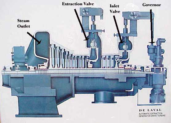
Note: Please see the enclosed cross-section of a typical single automatic-extraction, condensing turbine below. Notice the secondary steam (extraction) valves and secondary control stage downstream of these valves. Also note that the height of blades in the first few stages in the IP section is similar to the height in the first few stages in the HP section due to smaller mass flow in the IP section.
De_Laval_Auto-Extr_ST_r7y13n.jpg

For your LP section, a straight line represents the expansion through this section with a flattening curve at the end which represents the exhaust loss.
The GE method simplifies the expansion line by substituting an equivalent (straight line) efficiency to the final exhaust point. This simplification allows you to use a spreadsheet, rather than a sophisticated modeling program, to estimate turbine performance.
You did not answer how you determined the amount of steam flow in the uncontrolled extraction. You could model this extraction in your spreadsheet if it is for a feedwater heater.

Again, if you need a better estimate, I suggest that you contact a turbine manufacturer to obtain a heat balance and an extraction performance map.
Best of luck!
 
Dear Stgrme,
many thanks for your feedback.
Let me check now with some steam turbine manufacturers...
With best regards,
Gabriele
 
Status
Not open for further replies.

Part and Inventory Search

Sponsor