Hi everyone. I've been playing around with representing GD&T concepts graphically in Solidworks, and I'm getting a little confused.
Consider the following hole:
-Size tolerance of 1.4/1.0
-Perpendicularity tolerance of .1 @MMC referenced to datum "A", which is a surface perpendicular to the nominal hole axis.
My assumption is that I can inspect this callout in one of two ways:
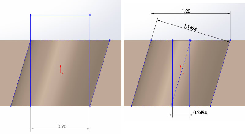
1. Calculate the virtual condition of the hole (MMC hole diameter-MMC tolerance zone diameter=.9). Check that a .9 diameter cylindrical boundary, held perpendicular to Datum A, can pass through the hole while datum feature A on the part is also constrained to Datum A.
2. Find the Unrelated Actual Mating Envelope of the hole. Calculate the bonus tolerance ([UAME diameter]-[MMC diameter]). Verify that the axis of the UAME is contained within the tolerance zone.
See the attachment for the example I drew up, showing a section view of an as-produced hole. Method 1 checks out; the hole can (barely) clear a .9 cylinder held perpendicular to datum A. However, with Method 2 the part doesn't pass; I've measured the UAME diameter (1.1494) and used that to calculate the tolerance zone diameter (.2494), but the UAME axis doesn't fit in the tolerance zone. In order for everything to work out just right, I would have to have measured the "size" of the hole parallel to datum A (1.20), instead of using the UAME.
Was I wrong in using [UAME diameter]-[MMC diameter] to calculate bonus tolerance? How can I explain the discrepancy between the two methods?
Thank you!
edit: fixed file upload
edit2: Never mind, all of the files I post have their name appended to their first 2 characters and show nothing when opened. I apologize if the image in the post messes up formatting for anyone.
Consider the following hole:
-Size tolerance of 1.4/1.0
-Perpendicularity tolerance of .1 @MMC referenced to datum "A", which is a surface perpendicular to the nominal hole axis.
My assumption is that I can inspect this callout in one of two ways:
1. Calculate the virtual condition of the hole (MMC hole diameter-MMC tolerance zone diameter=.9). Check that a .9 diameter cylindrical boundary, held perpendicular to Datum A, can pass through the hole while datum feature A on the part is also constrained to Datum A.
2. Find the Unrelated Actual Mating Envelope of the hole. Calculate the bonus tolerance ([UAME diameter]-[MMC diameter]). Verify that the axis of the UAME is contained within the tolerance zone.
See the attachment for the example I drew up, showing a section view of an as-produced hole. Method 1 checks out; the hole can (barely) clear a .9 cylinder held perpendicular to datum A. However, with Method 2 the part doesn't pass; I've measured the UAME diameter (1.1494) and used that to calculate the tolerance zone diameter (.2494), but the UAME axis doesn't fit in the tolerance zone. In order for everything to work out just right, I would have to have measured the "size" of the hole parallel to datum A (1.20), instead of using the UAME.
Was I wrong in using [UAME diameter]-[MMC diameter] to calculate bonus tolerance? How can I explain the discrepancy between the two methods?
Thank you!
edit: fixed file upload
edit2: Never mind, all of the files I post have their name appended to their first 2 characters and show nothing when opened. I apologize if the image in the post messes up formatting for anyone.