Continue to Site

Eng-Tips is the largest engineering community on the Internet

Intelligent Work Forums for Engineering Professionals

  • Congratulations KootK on being selected by the Eng-Tips community for having the most helpful posts in the forums last week. Way to Go!

Confused with Angular Momentum 2

Status
Not open for further replies.

Keithkingdon1st

Mechanical
Sep 14, 2016
7
Hello everyone,

I have a problem that I was asked. The company that I work for is building a fatigue testing machine, they asked me to calculate a component of said machine. The part I am calculating is the safety leash/lasso that would keep the shaft from destroying the machine in the event that the shaft breaks in half.

So the problem is; a 40000 lb. perpendicular force is applied to the end of an initially stationary 6 foot section with the other end attached to a pivot point. The section is a hollow mild steel tube with OD 9.625in and ID 8.8.35in. I must find the force required to stop the shaft when it rotates 90degrees neglecting gravity.

I can’t seem to figure out this problem. Converting to SI I get the following:

Moment applied of the end = 325396.308 Nm
Mass of section = 88 kg
Radius of Gyration = 0.08296 m
Moment of Inertia = 0.6056 kgm2
Angular Acceleration = 537312.26 rad/sec2
Angular Velocity at 90 degrees = 537.31 rad/sec
Angular Momentum = 325.396 kgm2/sec
Force required to stop = Original 40000lbs

The supervisor says he would like the shaft to go 0 degrees to 90 degrees in about 1ms

The equations I used are:
Torque = Force x Distance
Inertia = Mass x Radius of Gyration
Radius of Gyration = ((D2+d2)1/2)/4
Angular Acceleration = Torque/Inertia
Angular Velocity = Angular Acceleration x Time
Angular Momentum = Inertia x Angular Velocity

I have tried to solve the problem many times but have gotten nowhere. Any advice on where I am making a mistake? Would the force required to stop the shaft be the initial 40000 lbs put into the system?

Thanks
 
Replies continue below

Recommended for you

If I'm picturing it correctly you need to see how much kinetic energy the shaft has right before it catches the leash. Assume all that energy is used to stretch the sling. Then treat the sling as a spring that has stored all the energy by stretching.
 
A picture would help us, and may even help you.

You used an equation that included distance, but I don't see anything you've listed as being called the "stopping distance"

TTFN (ta ta for now)
I can do absolutely anything. I'm an expert! faq731-376 forum1529
 
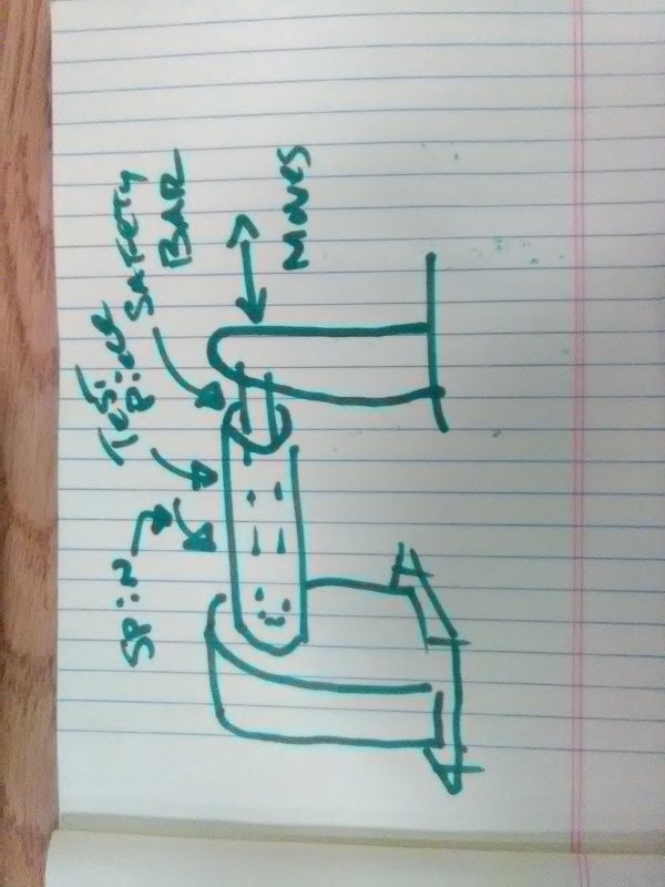
Okay, I've linked a picture I quickly sketched.

The distance in the torque equation was the distance(6feet) that the force was applied, from the pivot point. What if instead of saying stopping distance for the sling or elastic forces, I said the end of the shaft hit a wall and stopped. Could we find the force of the impact and imagine the sling had no elastic properties or say the impact takes 1ms? That way, the force we find would be the highest we would see from the machine and have a real high shock load for safety reasons.

Thanks
 
 http://files.engineering.com/getfile.aspx?folder=9e8197ac-38b3-4d7f-a957-2a66b9125304&file=IMG_2770.jpg
Imagining the sling has no elastic properties will make the problem insoluble - you'll just end up with infinite forces.

It's an analagous approach to hitting an immovable object with an unstoppable force - something that makes entertaining political, and poor engineering, analysis.

A.
 
Keithkingdon1st,

Is your figure a mechanism, or are you visualizing your failure mode?

--
JHG
 
Keithkingdon1st,

Also, is your 40000lb force continuous, or does it have a time duration?

--
JHG
 
Drawoh,

I am visualizing this in failure after the shaft breaks. The force is not continuous, the force will only be applied for calculation purposes, 1ms.

Thanks
 
Keithkingdon1st,

I am still looking at your problem. Does your shaft travel 90[°] in 1ms[ ](.001s)? I work that out to be 15000rpm, average. Would your steel shaft remain intact under those conditions, lasso or no lasso?

--
JHG
 
Drawoh,

I was given that number by my supervisor, it doesn't seem correct. I can't imagine the shaft would survive rotating that fast to a stop. Ill talk to my boss tomorrow and see what he has to say.

Thanks for helping
 
Have you looked at an impulse/momentum approach?
Torque x impulse time = I x angular velocity change

Ted
 
hydtools,

I had used the impulse/momentum to assume 1ms of stopping time in that equation. That is how i got the 40000lb impulsive force back. My boss is back today so I will grill him with some questions.
 
I spoke with my supervisor to get some clarity. He changed gears and would like me to calculate the momentum when the shaft reaches 90 degrees, then research some wire rope/slings to find some elasticity values. With the values I can find the stopping distance and hopefully the shock load that the sling will need to withstand.

I'm fairly confident that I can get these numbers but any advice on how I should proceed with the calculations would be much appreciated.

Thanks everyone.
 
Keithkingdon1st,

So, there is no hinge mechanism. What you have is conditions catastrophic enough to bend a Ø9.625"[ ]tube 90[°], with all sorts of buckling, and possibly an outright fracture. If your sling will work, it must be way stronger than the cantilevered tube.

I think a better safety device would be a very sturdy ring at the floating end of the shaft. If the ring has a clearance of 1/4" or 1/2", the shaft will rotate freely until it fails and bends a bit. There will be horrible noises, but probably no flying parts. A slings sounds to me orders of magnitude weaker than what you need.

--
JHG
 
Ring containment is the sort of thing I was thinking too. You could also invert that and have a safety bar that extended from the free end to the driven end. Then the really dangerous sort of thing (instead of merely real expensive) like the test piece flying off and killing someone is made not inconceivable, but the result of many unlikely failures. See my sketch for clarification.
IMG_20160915_125206_gvk093.jpg
 
You might research and apply driveshaft/PTO safety and enclosure as well.
 
drawoh,
moon161,

The test piece will have a flange on one end that will be attached to a u-joint. I see the u-joint as a pivot point to simplify calculations. We will be applying the 20 Ton force in the middle of a 12' shaft, we want to test for catastrophic failure. The test piece will rotate but be mounted on both ends of the shaft (I realize I had drawn my sketch without one end). I never thought of the safety for driveshaft and PTO, I'll take a look at that. We had planned to have two slings, one on either half of the shaft.
 
Status
Not open for further replies.

Part and Inventory Search

Sponsor