Eng-Tips is the largest engineering community on the Internet

Intelligent Work Forums for Engineering Professionals

  • Congratulations waross on being selected by the Tek-Tips community for having the most helpful posts in the forums last week. Way to Go!

Confusion Regarding the Dead Load in ASCE Load Combination 5 and 7

Status
Not open for further replies.

azureblue83

Structural
Jan 26, 2015
17
0
0
US
Load Combination 5 and 7:
1.2D+1.0E+L+0.2S
0.9D+1.0E
where D is defined as simply "dead load" and E = earthquake load, calculated as following:
E = E[sub]h[/sub] +- E[sub]v[/sub] = pQ[sub]E[/sub] +- 0.2S[sub]DS[/sub]D
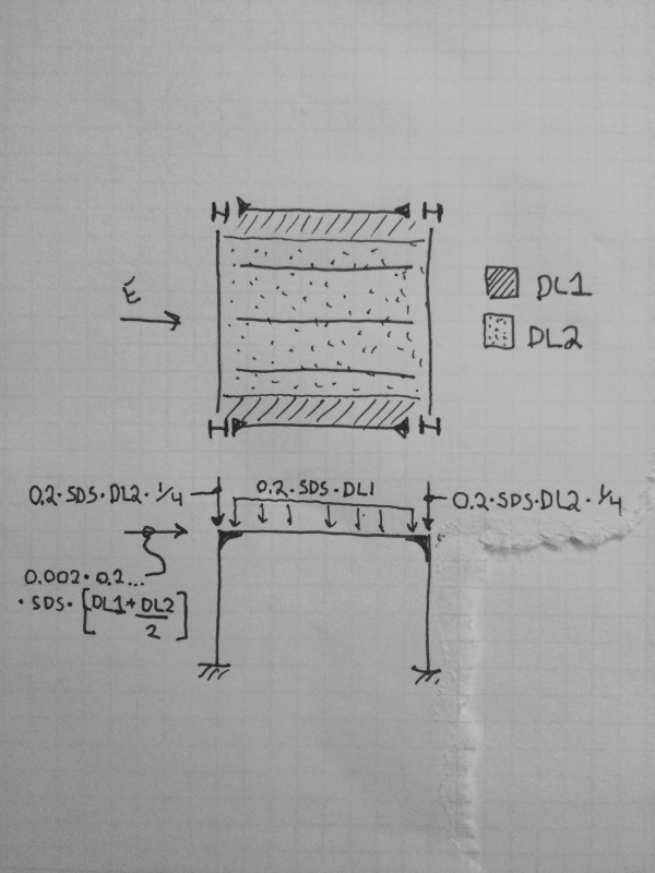
where Q[sub]E[/sub] is the effect of horizontal seismic effect, and 0.2S[sub]DS[/sub]D is the vertical seismic effect.

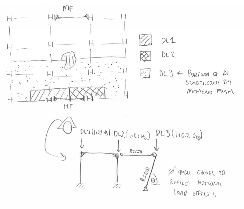
Now, suppose designing a moment frame that is for lateral load only, i.e. it is not taking any dead/live load except its self weight, but it is taking seismic lateral load due to building's dead load. What "D" should be used for the 0.2S[sub]DS[/sub]D? Do we use the building's D? Or, just the moment frame's self weight D?
 
Replies continue below

Recommended for you

I would say that you would want to include a leaning column with the dead load of the portion of the structure that relies on the frame for lateral stability. and you would use the 0.2Sds modifier if the SDC requires it.
 
So in another word, we could end up with a situation where:

1.2D[sub]1[/sub]+1.0(pQ[sub]E[/sub] + 0.2S[sub]DS[/sub]D[sub]2[/sub])+L+0.2S

where D[sub]1[/sub] is the moment frame's self weight dead load; and D[sub]2[/sub] include the frame's self weight plus the part of the building's dead load that the frame is taking lateral load from.

Interesting.
 
The dead load "D" is that load that is applied to the frame...not the overall building dead load that doesn't impart load to the frame.

Just like you would use the seismic load (from the attached tributary dead loads) that are applied to the frame.
I guess I'm not sure why the question at all?


Check out Eng-Tips Forum's Policies here:
faq731-376
 
The question was: are the D's that appear in the load combination (1.2D and the 0.2S[sub]DS[/sub]D) the same D, or can they be different.

In ASCE 7-10 12.4.2.3, they seem to say that the D should be the same D:
"...the following seismic load combination...shall be used in lieu of the seismic load combination in Section 2.3.2 or 2.4.1"

5. (1.2 + 0.2S[sub]DS[/sub])D + pQ[sub]E[/sub] + L + 0.2S
..."

Here, you see they are suggesting the D being the same for 1.2D and 0.2S[sub]DS[/sub]D.

But we just discussed a case where the D can be different.
 
The D's are the dead loads applied to your frame.
There is no difference between them.
One is a gravity effect and one is the vertical effect of the seismic event on that dead load.


Check out Eng-Tips Forum's Policies here:
faq731-376
 
This is an interesting question. And I think that RobertHale nailed it. I believe my sketch below to be a graphical representation of RobertHale's suggestion. You would take the seismic amplified dead loads shown in the frame elevation and plug them into your usual load combinations.

Capture_b4c7cw.png


I like to debate structural engineering theory -- a lot. If I challenge you on something, know that I'm doing so because I respect your opinion enough to either change it or adopt it.
 
KootK - Not sure about that. Does bringing in D3 in your sketch, and using it to add to the lateral seismic effect E, follow the intent of what 0.2SDS(D) was meant to do?

I've always understood that the 0.2SDS factor on D was intended to deal with the vertical accelerations of the seismic event and how they add to or subtract from the static dead load D.

In your sketch, you are attempting to take a 0.2SDS amount of dead load and create a lateral load effect on the frame.
Isn't it correct that the typical rho x QE seismic demand value, along with the direct design method, already takes notional load effects into account?

Now if you had some purposely angled columns in the framework then I could see the vertical seismic effect on D creating additional lateral effects on the frame via 0.2SDS(D).

Your sketch is dealing with someone modeling the frame as a 2D entity and then attempting to manually bring in loads to it to account for the combinations.
If you had a full 3D model of the entire building, you would simply apply the loads to the model, apply the combinations (1.2D+1.0E+L+0.2S or 0.9D+1.0E) with E = Eh +- Ev = pQE +- 0.2SDS(D), and get your results.
There would be no need to add fictitious rigid members with phi angles.


Check out Eng-Tips Forum's Policies here:
faq731-376
 
JAE said:
KootK - Not sure about that.

Me neither. I welcome the debate.

JAE said:
Does bringing in D3 in your sketch, and using it to add to the lateral seismic effect E, follow the intent of what 0.2SDS(D) was meant to do?

In my mind it does. The whole building tributary vertical seismic load (WBTVSL) generates a lateral load on any out of plumb columns that rely on the moment frames for lateral stability. The WBTVSL also adds to the P-delta burden on those same columns. If this effect is accounted for elsewhere in the process, then that's news to me. I feel that it should be accounted for somewhere, however.

One interesting feature is that the vertical seismic loads are transitory, cyclical, and short lived. Perhaps they could disappear before P-delta buckling gets rolling? But then who knows how fast a thing buckles?

JAE said:
Isn't it correct that the typical rho x QE seismic demand value, along with the direct design method, already takes notional load effects into account?

It definitely takes notional loads into effect. But notional loads only deal with the destabilizing effect of the 1/500 out of plumb imperfection. They don't include the lateral loads that result when the WBTVSL acts on those out of plumb columns. They also don't capture the contribution of the WBTVSL to the system's P-delta burden.

JAE said:
If you had a full 3D model of the entire building, you would simply apply the loads to the model, apply the combinations (1.2D+1.0E+L+0.2S or 0.9D+1.0E) with E = Eh +- Ev = pQE +- 0.2SDS(D), and get your results. There would be no need to add fictitious rigid members with phi angles.

Your approach, like mine, already includes the destabilizing effect of the WBTVSL on the P-delta burden.

[1.2D + 1.0E] = [1.2D + 1.0Eh + 1.0Ev] = [1.2D + 1.0Eh + 1.0 x 0.2SDS x D] = [(1+0.2SDS)D + 1.0Eh].

As your 3D model moved laterally, [0.2 x SDS x DL_[whole building]] would be contributing to P-delta instability I think. The difference with my approach is that I would add (0.002 WBTVSL) to the notional loads.

I like to debate structural engineering theory -- a lot. If I challenge you on something, know that I'm doing so because I respect your opinion enough to either change it or adopt it.
 
Well as to PDelta effects on the overall building - the IBC and ASCE 7 do include provisions when PDelta needs to be included in the analysis (That theta parameter).


Check out Eng-Tips Forum's Policies here:
faq731-376
 
It's also worth noting that 0.002 x 0.2 x SDS x D is about equivalent the wind pressure generated by the flap of a butterfly wing. That part gets lost in the noise. Even I wouldn't bother if it didn't fall out of a spreadsheet automatically.

I like to debate structural engineering theory -- a lot. If I challenge you on something, know that I'm doing so because I respect your opinion enough to either change it or adopt it.
 
In the interest of precision, we need to distinguish between loads that are tributary to the frame in a gravity sense and those that are tributary to the frame in a stability sense. Those are obviously not the same thing.

The notional loads applied to the frame will have a dead load component. And that component will, in general, include contributions from dead loads that are not directly tributary to the frame in a gravity sense.

In a second order P-delta analysis (DAM), dead loads not directly tributary to the frame in a gravity sense will generate lateral dead loads on the frame as those non-tributary dead loads shift laterally in space.

I like to debate structural engineering theory -- a lot. If I challenge you on something, know that I'm doing so because I respect your opinion enough to either change it or adopt it.
 
The load combinations in chapter 12 show the intent clearly.
(1.2 + 0.2S[sub]DS[/sub])D + ρE + L + 0.2S
(0.9 - 0.2S[sub]DS[/sub])D + ρE
 
I'm afraid that doesn't resolve anything for me WannabeSE. What does it say to you?

I like to debate structural engineering theory -- a lot. If I challenge you on something, know that I'm doing so because I respect your opinion enough to either change it or adopt it.
 
@wonnabeSE

for the 1.2D, the D is the dead load the member is supporting.

for the 0.2S[sub]DS[/sub]D, the D is the dead load that's causing the seismic lateral load.

They DO NOT have to be the same D. If they are not the same D, (1.2 + 0.2S[sub]DS[/sub])D + ρE + L + 0.2S does not apply.

For a simple example:

ex_kqcchg.png


The floor dead load are supported by Beam A and B, not by 1 and 2.

Designing Beam 1 and 2, the 1.2D is only their self weight. But the 0.2S[sub]DS[/sub]D is from half of the floor dead load plus the beam self weight.

(1.2 + 0.2S[sub]DS[/sub])D + ρE + L + 0.2S in this case I think do not apply.
 
@Azureblue:

For vertical load applied to any member, the D used for [0.2 x SDS x D] is the same D as that used for regular gravity design.

It is only the lateral and stability loads that need to be based on the larger D that generates the seismic load. At least that's my take on it.

I like to debate structural engineering theory -- a lot. If I challenge you on something, know that I'm doing so because I respect your opinion enough to either change it or adopt it.
 
Here's my interpretation of how your example should be handled Azureblue.

image_ikwtix.jpg


I like to debate structural engineering theory -- a lot. If I challenge you on something, know that I'm doing so because I respect your opinion enough to either change it or adopt it.
 
You are right. I thought the dead load in DL2 would have vertical seismic effect in Beam 1 and 2. Now I think about it, they would only affect the columns and Beam A and B, not 1 and 2. Although, in practice, the floor is probably one piece and Beam 1 and 2 would essentially receive some vertical seismic effect from DL2; it's conservative to design Beam 1 and 2 for it.
 
KootK said:
It is only the lateral and stability loads that need to be based on the larger D that generates the seismic load. At least that's my take on it.
Horizontal seismic forces are based on the effective seismic weight, w or W. For any given level, the effective seismic weight, w[sub]x[/sub], is frequently (almost always) different than the total dead load to the level. Effective seismic weight is frequently called seismic mass.

Vertical seismic forces are proportional to the dead loads on each members. The vertical seismic force is applied to all framing not just the lateral framing.
 
Status
Not open for further replies.
Back
Top